64
Set the signal to be always
valid
Input always close signal
from SIx
to 0V
0V
Note: if the distributed terminal has other signal, set the signal to other terminal or set to unused.
The setting range of input terminal for each type:
DS2-20P4
DS2-20P7
n.0000~n.0002
n.0010~n.0012
n.0010~n.0014
DS2-2□P□-B
n.0010~n.0016
Because the input terminal quantity is different for each
type, the setting range is different.
Example: take the input signal /CLR (P5-24) of DS2-20P7 as an example to explain the
terminal distribution.
5-12-2. Default setting of input terminal
SI1 SI2 SI3 SI4 SI5 SI6
DS2-20P4
DS2-20P7
DS2-2□P□-B
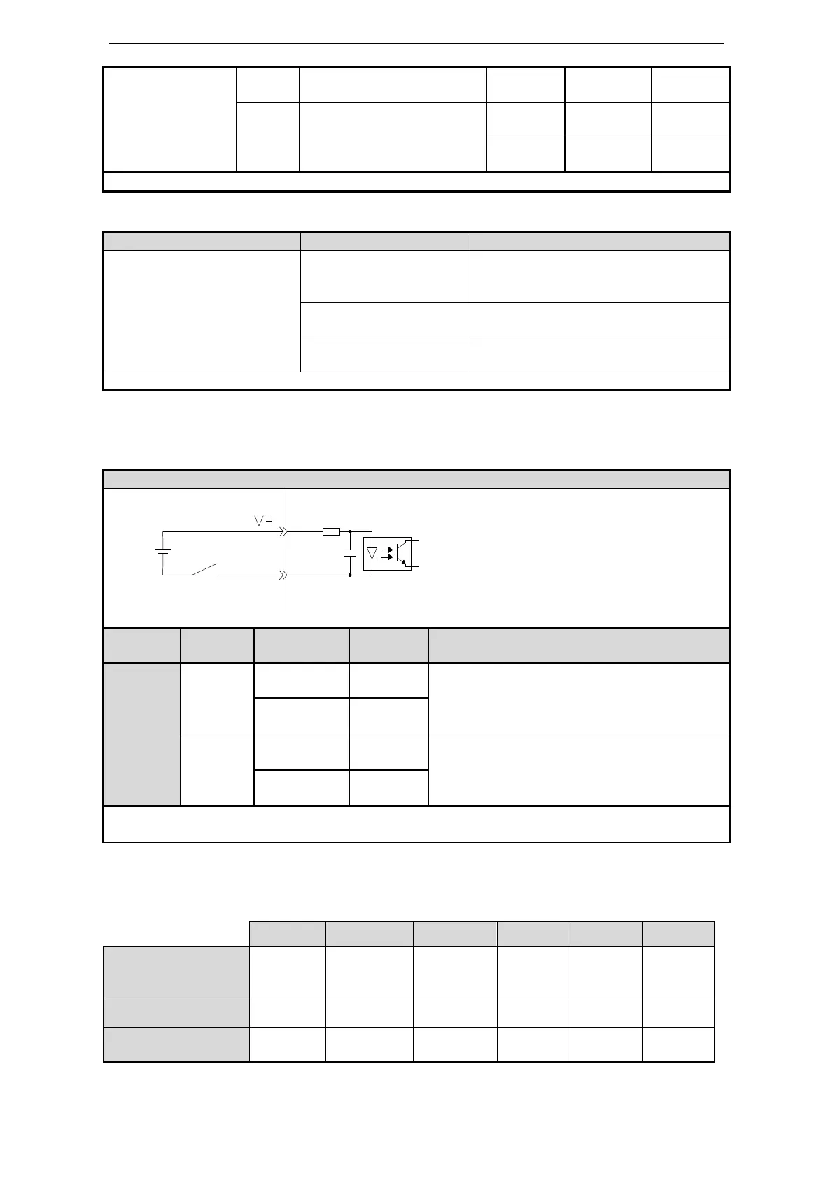
Wiring example of input signal
Terminal 7 of DS2-20P7 is +24V, terminal 6 is SI2.
/CLR is distributed to SI2.
state
state
to 0V
Clear the pulse offset at the moment of SI2 and
0V connected
0V
to 0V
Clear the pulse offset at the moment of SI2 and
0V disconnected
0V
Note: the default input of SI2 is
terminal or set to unused.
0V
24V
7
6
3.3KΩ
/SI2

 Loading...