15
3-2-3.I/O Signal Names and Functions
The following section describes servo driver I/O signal names and functions.
Input Signals
Digital input
SI1~SI6
Multi-functional input terminal 5-12-1
Pulse input
PUL-
PUL+
P2-00=1:A-phase pulse
P2-00=2:pulse
5-3-2
DIR-
DIR+
P2-00=1:B-phase pulse
P2-00=2:pusle direction (sign)
5-3-2
Output Signals
Digital Output SO1~SO3 Multi-functions Output Terminals 5-12-2
Notes: the control signal must be grounded, please refer to chapter 3-4.
3-2-4.Interface Circuits
This section shows examples of servo driver I/O signal connection to the host controller.
The interface with the command input circuit
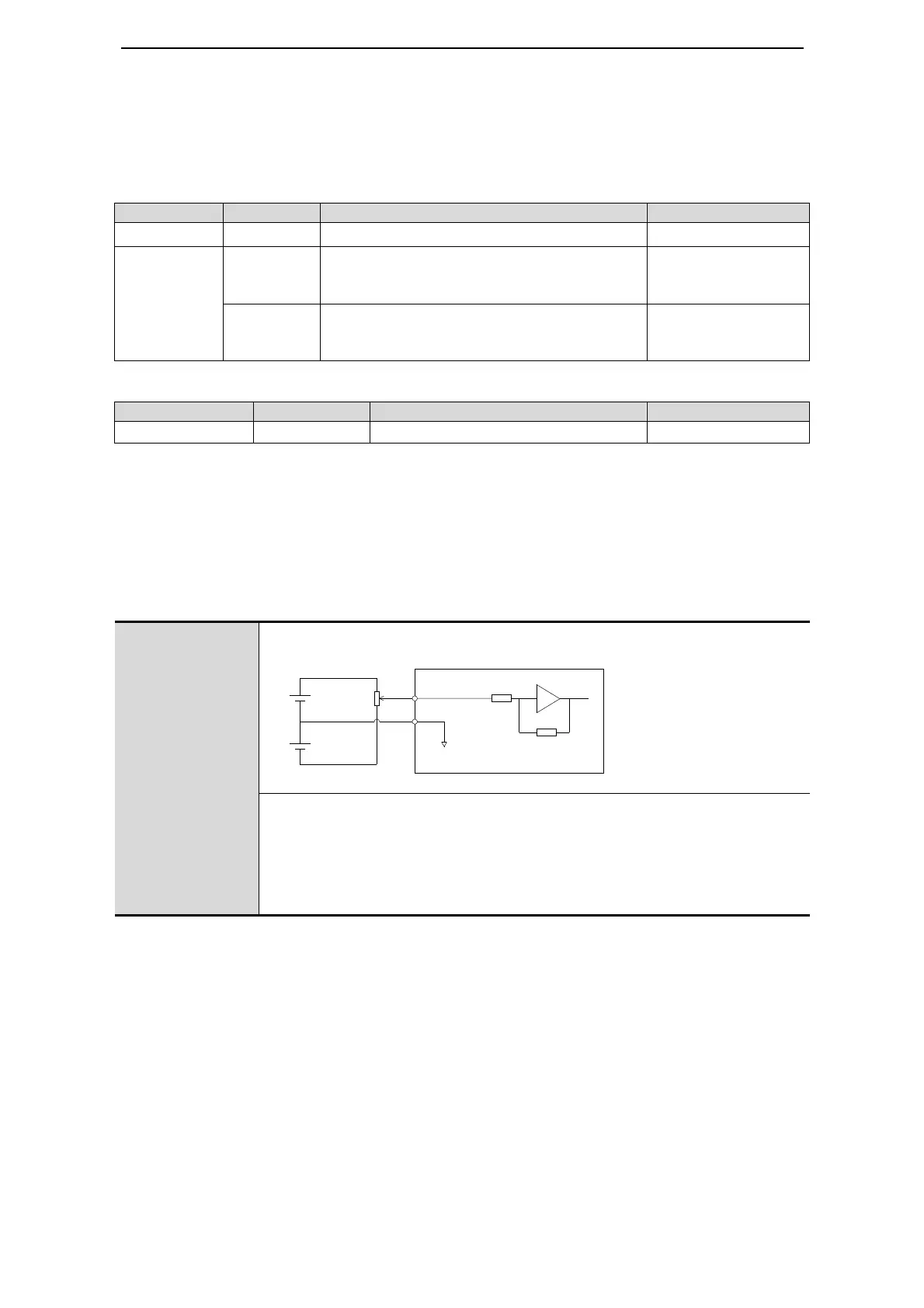
(1) Analog input circuit
DS2-2□P□-A
DS2-2□P□-B
Host device servo drive
The analog signal is speed command or torque command. The input
impedance is shown as below.
• speed command input: about 13KΩ
• torque command input: about 13KΩ
• max allowed voltage of input signal: ±10V
(2) Position command input circuit
+10V
-10V
11 T-REF
12 V-REF
13 GND
0V
R=13KΩ
2KΩ
1W

 Loading...