5-2
E
POWR
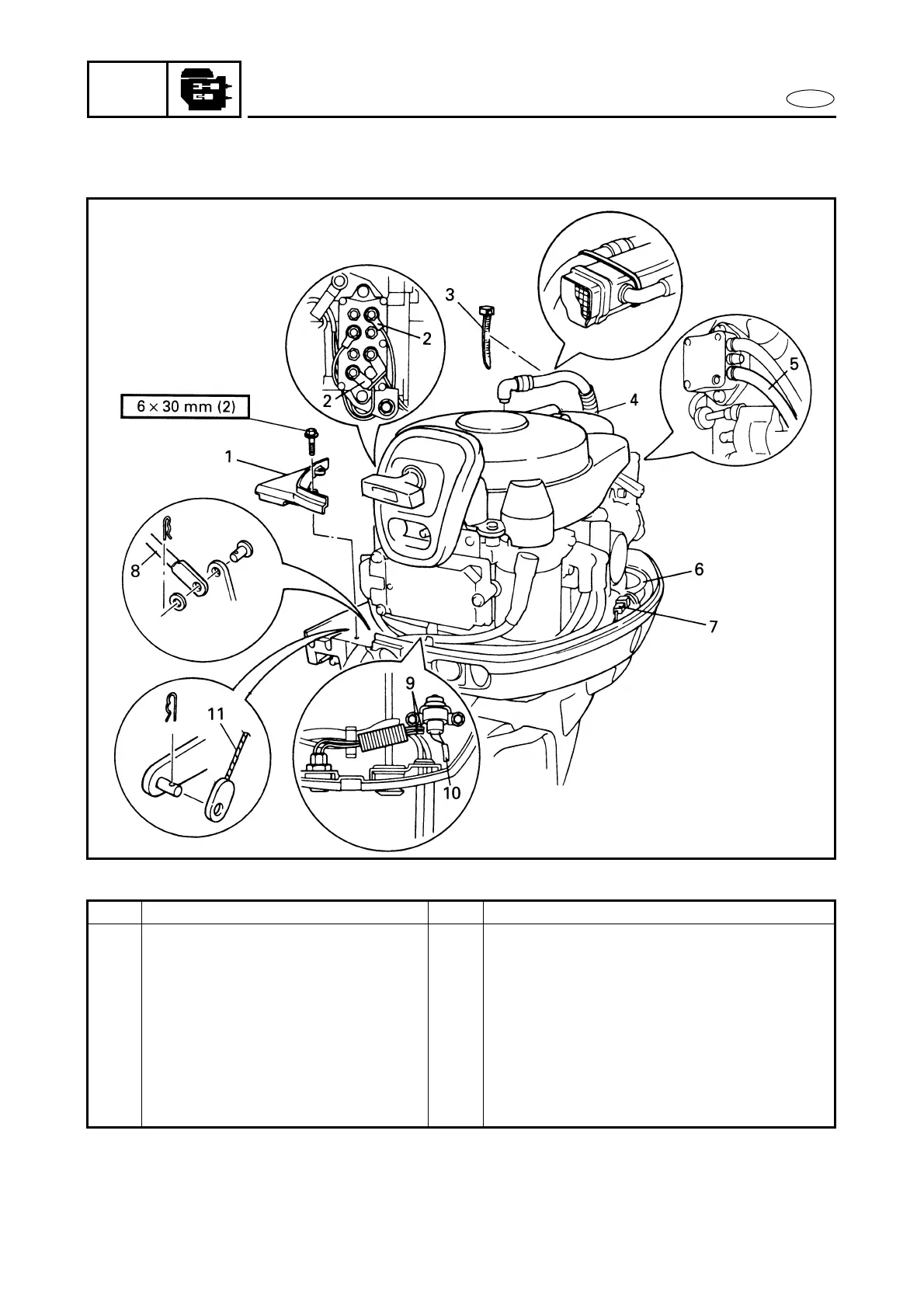
POWER UNIT
EXPLODED DIAGRAM
Step Procedure/Part name Q’ty Service points
5 Fuel hose
(fuel filter-to-fuel pump)
1
6 Pilot water hose 1
7 Trailer switch coupler (EHT, ET) 1 3 pins
8 Shift link rod 1
9 Starter switch lead (EH, EHT) 2
10 Neutral switch lead (EH, EHT) 2
11 Start-in-gear protection device
wire (MH)
1
 Loading...