3-1
CHAS
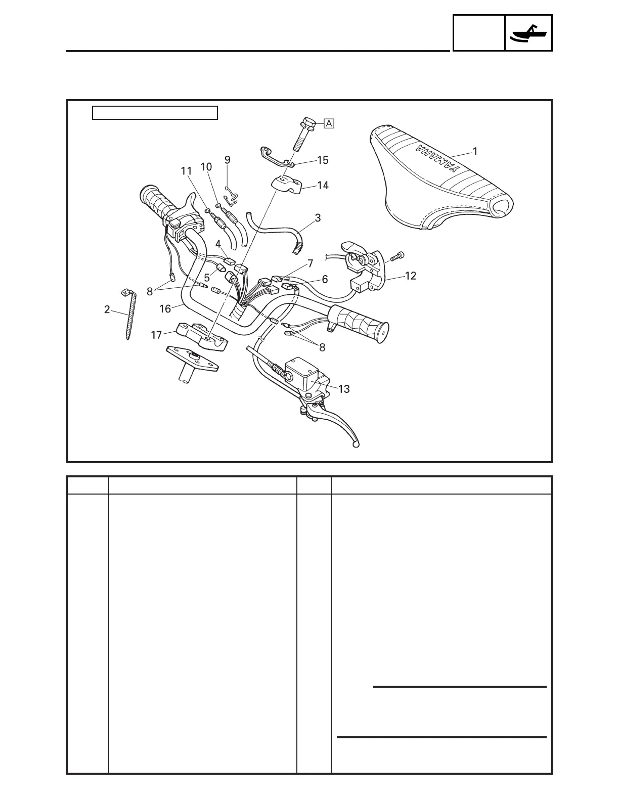
STEERING
CHASSIS
STEERING
15 Nm (1.5 m • kg, 11 ft • lb)
Å:
Remarks
Remove the parts in the order listed below.
Disconnect.
Disconnect.
Disconnect.
Disconnect.
Disconnect.
NOTE:
After installing all parts, refer to “CABLE
ROUTING” in CHAPTER 9, to check the cable,
lead and hose routings.
For installation, reverse the removal proce-
dure.
Order
1
2
3
4
5
6
7
8
9
10
11
12
13
14
15
16
17
Job name/Part name
Handlebar removal
Handlebar cover
Plastic band
Oil tank breather hose
Thumb warmer coupler
Engine stop switch coupler
Brake switch coupler
Headlight beam switch coupler
Grip warmer lead
Throttle cable holder
Throttle cable
Oil pump cable
Brake lever holder
Master cylinder assembly
Handlebar holder (upper)
Cable holder
Handlebar
Handlebar holder (lower)
Q’ty
1
3
1
1
1
1
1
4
1
1
1
1
1
2
1
1
1
SDN3010
 Loading...