5-5
ENG
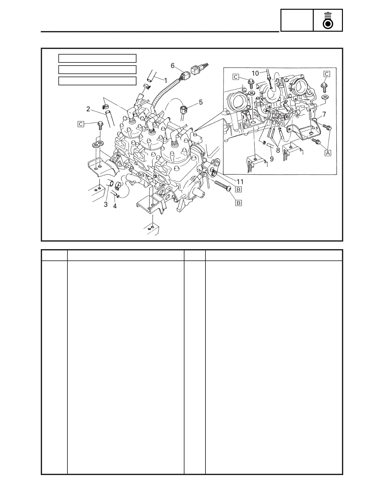
ENGINE ASSEMBLY
ENGINE ASSEMBLY
33 Nm (3.3 m • kg, 24 ft • lb)
Å:
40 Nm (4.0 m • kg, 29 ft • lb)
ı:
50 Nm (5.0 m • kg, 36 ft • lb)
Ç:
Order
1
2
3
4
5
6
7
8
9
10
11
Remarks
Remove the parts in the order listed below.
Refer to “EXHAUST ASSEMBLY”.
Refer to “CARBURETORS” in CHAPTER 7.
Refer to “YAMAHA POWER VALVE SYSTEM
(Y.P.V.S.)”.
Refer to “RECOIL STARTER”.
Refer to “AC MAGNETO”.
Refer to “PRIMARY SHEAVE AND DRIVE V-
BELT” in CHAPTER 4.
Drain. Refer to “COOLANT REPLACEMENT”
in CHAPTER 2.
Disconnect.
Disconnect.
Disconnect.
Disconnect.
Disconnect.
Disconnect.
Disconnect.
Loosen.
For installation, reverse the removal proce-
dure.
Q’ty
1
1
1
1
1
1
1
3
1
1
1
Job name/Part name
Engine removal
Exhaust assembly
Carburetors
Y.P.V.S.
Recoil starter
AC magneto
Primary sheave
Coolant
Coolant hose 1
Coolant hose 2
Coolant hose 3
Carburetor heating hose
Thermo sensor coupler
Ignition coil coupler
Rear bracket (right)
Oil hose
Vacuum hose
Oil pump cable
Mounting bolt
SDN5040