1
3
5
7
9
0
F
I
L
4
6
8
G
K
MN
CHAS
POWR
TR
ENG
COOL
–+
ELEC
GEN
INFO
SPEC
H
J
B
M
G
E
5
LT
M
CARB
INSP
ADJ
2
A
CDE
B
O
New
T
R
.
.
LS
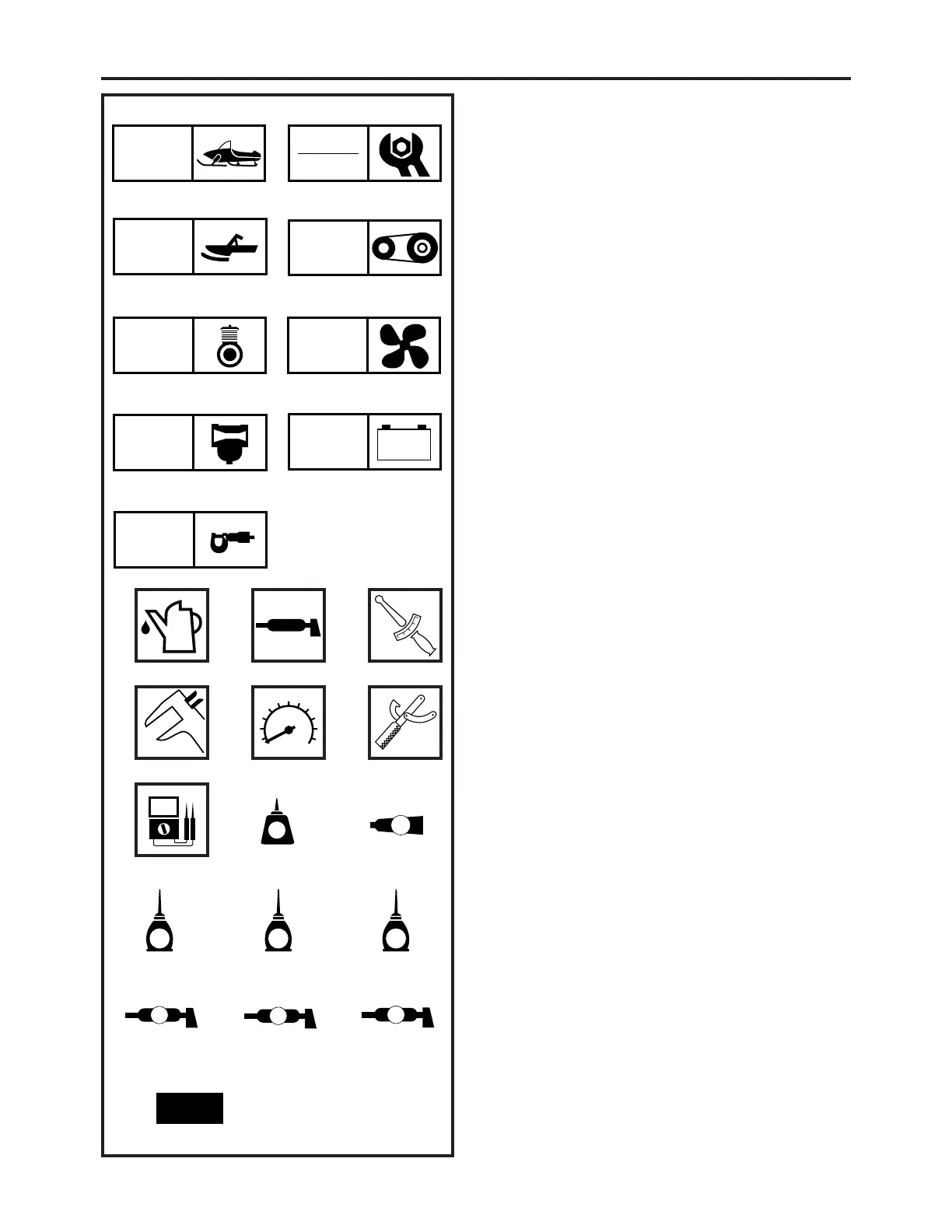
ILLUSTRATED SYMBOLS
(Refer to the illustration)
Illustrated symbols 1 to 9 are designed as thumb
tabs to indicate the chapter’s number and con-
tent.
1 General information
2 Periodic inspection and adjustment
3 Chassis
4 Power train
5 Engine
6 Cooling system
7 Carburetion
8 Electrical
9 Specifications
Illustrated symbols 0 to F are used to identify
the specifications which appear.
0 Filling fluid
A Lubricant
B Tightening
C Wear limit, clearance
D Engine speed
E Special tool
F Ω, V, A
Illustrated symbols G to O in the exploded dia-
gram indicate grade of lubricant and location of
lubrication point.
G Apply locking agent (LOCTITE
®
)
H Apply Yamabond No.5
®
I Apply engine oil
J Apply gear oil
K Apply molybdenum disulfide oil
L Apply wheel bearing grease
M Apply low-temperature lithium-soap base grease
N Apply molybdenum disulfide grease
O Use new one