2 - 23
SPEC
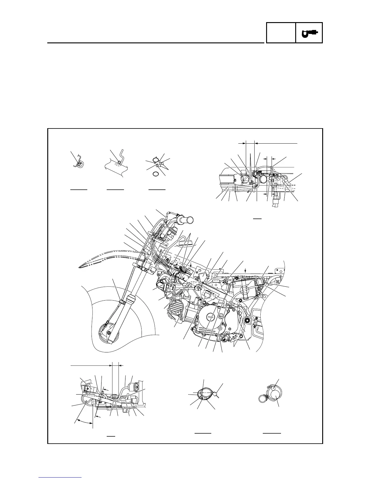
CABLE ROUTING DIAGRAM
Å Pass the start switch lead, main
switch lead, engine stop switch
lead and throttle cable through
the cable guide.
ı Pass the fuel tank breather hose
through the hose guide.
Ç Pass the carburetor breather
hose through the hose guide.
Î Fasten the carburetor heater lead,
main switch lead, engine stop
switch lead and start switch lead.
‰ After fastening the CDI mag-
neto lead, cut off any excess
from the plastic locking tie end.
Ï Fasten the battery leads to the
bracket with the plastic locking
tie. For fastening, pass the plas-
tic locking tie through the hole in
the bracket.
Ì After fastening the starter motor
lead, cut off any excess from the
plastic locking tie end.
Ó After fastening the CDI mag-
neto lead, cut off any excess
from the plastic locking tie end.
È Position the start switch coupler
and engine stop switch coupler
between the carburetor breather
hose and thermo switch.
Ô Make sure that the CDI unit lead
does not contact the thermo
switch bracket.
A
A
A
CC
D
B
B
B
B
FF
F
E
E
D
A - A B - B E - E
C
F - F G - G
D
K
K
Q
R
Ô
8
E
H
˜
2
3
4
6
5
4
3
2
1
J
I
H
G
F
E
D
C
B
A
0
Ï
9
8
Î
K
7
S
W
U
V
A
0
Í
T
9
9
Q
P
P
T
9
Ò
ˆ
Ø
Ç
ı
Å
Ó
Œ
Â
E
G
G
A
P
O
N
M
L
9
È
9
Ì
Ê
◊
25 mm (1.0 in)
∏
‰
35 ~ 45 mm
(1.38 ~ 1.77 in)
30 ~ 40 mm
(1.18 ~ 1.57 in)
Ë

 Loading...