2 - 25
SPEC
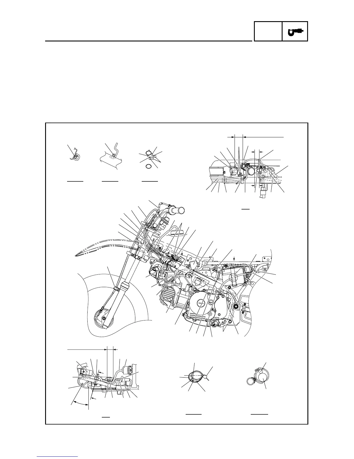
Í Pass the starter relay lead inside
the starter relay.
Ê Put the white tape ends within
the area as shown by the arrow.
Ë Make sure that the starting cir-
cuit cut-off relay lead does not
contact the spring (rear shock
absorber).
◊ Position the wire harness, CDI
magneto lead, thermo switch
lead and CDI unit lead as
shown.
A
A
A
CC
D
B
B
B
B
FF
F
E
E
D
A - A B - B E - E
C
F - F G - G
D
K
K
Q
R
Ô
8
E
H
˜
2
3
4
6
5
4
3
2
1
J
I
H
G
F
E
D
C
B
A
0
Ï
9
8
Î
K
7
S
W
U
V
A
0
Í
T
9
9
Q
P
P
T
9
Ò
ˆ
Ø
Ç
ı
Å
Ó
Œ
Â
E
G
G
A
P
O
N
M
L
9
È
9
Ì
Ê
◊
25 mm (1.0 in)
∏
‰
35 ~ 45 mm
(1.38 ~ 1.77 in)
30 ~ 40 mm
(1.18 ~ 1.57 in)
Ë
CABLE ROUTING DIAGRAM

 Loading...