ENGINE
Inspecting the Cylinder Block and Components
5-46 6LY3 Service Manual
© 2007 Yanmar Marine International
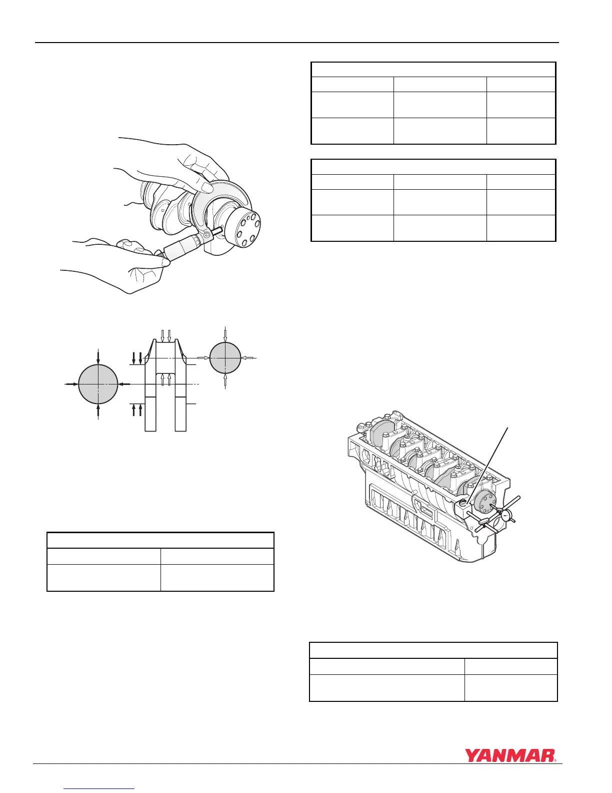
Measuring the Crank Pins and the Main
Bearing Journals
• Measure the outside diameter, roundness and
taper at each crank pin and journal as shown in
Figure 5-60 and Figure 5-61.
Figure 5-60
Figure 5-60
Figure 5-61
Figure 5-61
• Resurface the crankshaft pins and main bearing
journals if measurements exceed the listed
specifications.
• Replace if the defect is excessive.
NOTICE: To determine the oil clearance of the
crank pin, measure the inside diameter of the
connecting rod crank pin bearing.
Inspecting the End Play of the Crankshaft
• Assemble the crankshaft to the engine block.
• Tighten the main bearing caps to the specified
torque.
• Move the crankshaft along its horizontal axis from
end to end.
• Install a dial indicator (Figure 5-62, (1)) on one
end of the crankshaft to measure crankshaft end
play.
Figure 5-62
Figure 5-62
1 – Dial Indicator
• Replace the thrust bearing if it is worn beyond the
stated limit.
Crankshaft Pin and Main Bearing Journals
Item Limit (Diameter)
Roundness / Taper
0.01 mm
(0.0003 in.)
0005645
0005646
Crank Pin
Standard Limit
Outside Diameter
64.952-64.964 mm
(2.5571-2.5576 in.)
64.90 mm
(2.5551 in.)
Oil Clearance
0.036-0.093 mm
(0.0014-0.0036 in.)
0.160 mm
(0.0062 in.)
Crank Journal
Standard Limit
Outside Diameter
74.952-74.964 mm
(2.9508-2.9513 in.)
74.90 mm
(0.0062 in.)
Oil Clearance
0.036-0.093 mm
(0.0014-0.0036 in.))
0.15 mm
(0.0059 in.)
Crankshaft Side Clearance
Standard Limit
0.132-0.223 mm
(0.0051-0.0087 in.)
0.29 mm
(0.0114 in.)
0005647
(1)

 Loading...


