14.1 AI-01 (Analog Input) Module
14.1.8 Standard Cable Wiring Table
55
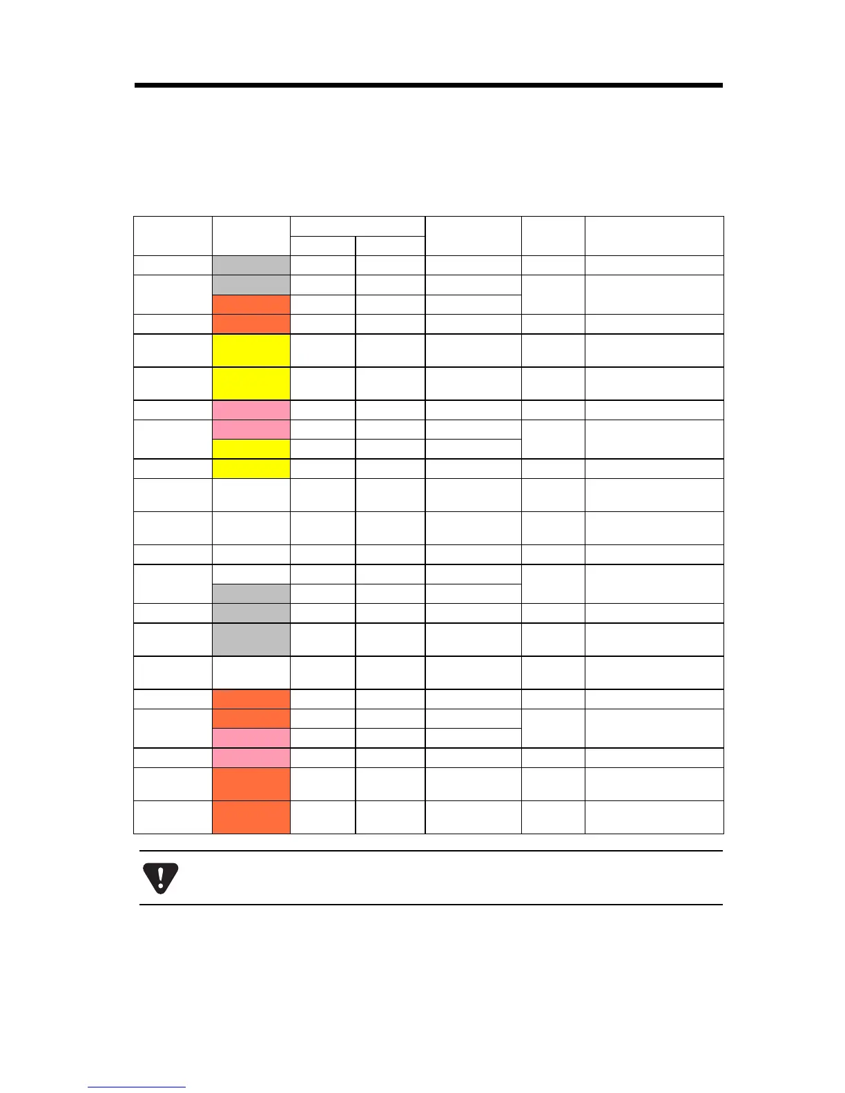
14.1.8 Standard Cable Wiring Table
The wiring table for the standard cable JEPMC-W6080- is shown
below.
Pin Wire Color
Marking
Label on Mark-
ing Tube
Signal
Name
Function
Color Marking
1
Gray Red
– – – V1/V5 V1/V5 Voltage input 1/5
2
Gray Black
– – – G1V/G5V
G1/G5 Ground 1/5
Orange Red
– – – G1A/G5A
3
Orange Black
– – – A1/A5 A1/A5 Current input 1/5
14
Yellow Red
–DP1/DP5
MDP1/
MDP5
Mode switching
terminal 1/5
16
Yellow Black
– DN1/DN5
MDN1/
MDN5
Mode switching
terminal 1/5
4
Pink Red
– – V2/V6 V2/V6 Voltage input 2/6
5
Pink Black
– – G2V/G6V
G2/G6 Ground 2/6
Yellow Black
– – G2A/G6A
6
Yellow Black
– – A2/A6 A2/A6 Current input 2/6
17
White Red
–DP2/DP6
MDP2/
MDP6
Mode switching
terminal 2/6
19
White Black
– DN2/DN6
MDN2/
MDN6
Mode switching
terminal 2/6
7
White Red
– – V3/V7 V3/V7 Voltage input 3/7
8
White Black
– – G3V/G7V
G3/G7 Ground 3/7
Gray Red
– – G3A/G7A
9
Gray Black
– – A3/A7 A3/A7 Current input 3/7
20
Gray Red
–DP3/DP7
MDP3/
MDP7
Mode switching
terminal 3/7
22
White Black
– DN3/DN7
MDN3/
MDN7
Mode switching
terminal 3/7
10
Orange Red
– – V4/V8 V4/V8 Voltage input 4/8
11
Orange Black
– – GV4/GV8
G4/G8 Ground 4/8
Pink Red
– – G4A/G8A
12
Pink Black
– – A4/A8 A4/A8 Current input 4/8
23
Orange Red
– – DP4/DP8
MDP4/
MDP8
Mode switching
terminal 4/8
25
Orange Black
– – DN4/DN8
MDN4/
MDN8
Mode switching
terminal 4/8
Columns “Label on Marking Tube”, “Signal Name”, and “Function” display the
values for connectors CN1 and CN2 in the format “CN1/CN2”, respectively.