2.1 Power Supply Connector
2.1.1 Specifications, Pin Arrangement, and Connection Procedure
9
2 Power Connections
2.1 Power Supply Connector
2.1.1 Specifications, Pin Arrangement, and Connection
Procedure
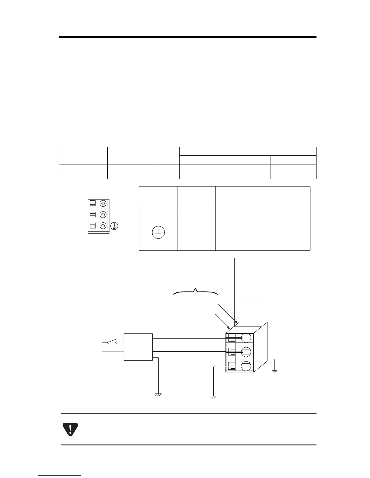
Supply 24VDC to the MP23iec. Connect the power supply
connector as shown in the diagram below.
Name Connector Name # of Pins
Connector Model
Module Cable Manufacturer
Power Supply
Connector
POWER
3
721-863 721-203/026 WAGO
Symbol Signal Name Description
24VDC
24V
24VDC input
0VDC
0V
0V input
FG
Frame ground
(Ground to 100 or less.)
Use an insulated 24VDC power supply. Attach the power supply switch on the
AC side. If the switch is attached on the 24VDC side, there will be an inrush
current of approximately 40A when the power is turned ON.