5.4 Operating Using Position Control with Pulse Train Reference
5-35
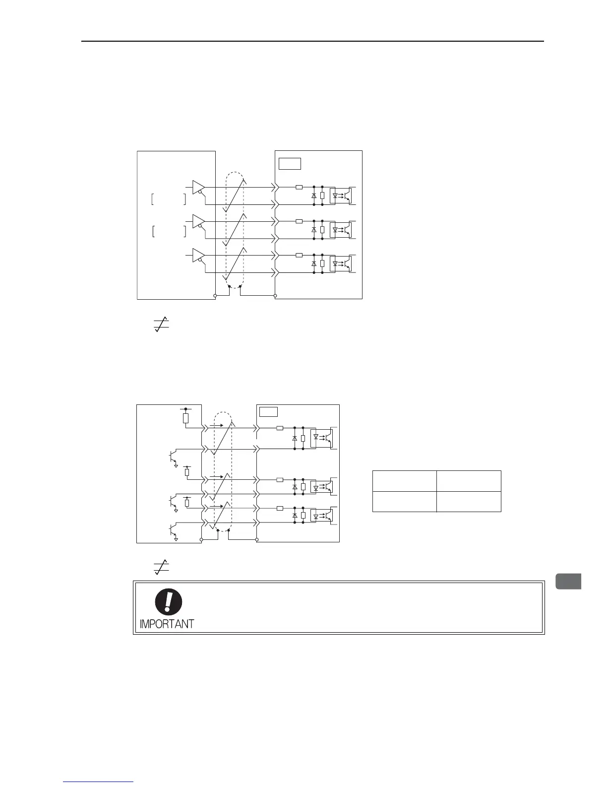
(3) Connection Example
Applicable line driver: SN75ALS174 manufactured by Texas Instruments Inc., or MC3487 or equivalent
Line Driver Output
∗ represents twisted-pair wires.
Open-collector Output
Set limit resistor R1 so the input current, i, falls between 7 mA to 15 mA.
∗ represents twisted-pair wires.
Line driver
SERVOPACK
Host controller
CN1
7
8
14
15
12
11
PULS
SIGN
CLR
/PULS
SIGN
/SIGN
CLR
/CLR
PULS
CW
Phase A
CCW
Phase B
∗
150Ω
4.7 kΩ
Photocoupler
150Ω
4.7 kΩ
Photocoupler
150Ω
4.7 kΩ
Photocoupler
FG FG
• Use a shielded cable for I/O signals and ground both ends of the shield.
• Connect the shield at the SERVOPACK to the connector shell so that the shield will
be connected to the frame ground (FG) through the connector.
SERVOPACKHost controller
CN1
7
8
14
15
12
11
/PULS
SIGN
/SIGN
CLR
/CLR
PULS
∗
Example
When Vcc is +12 V: R1 = 1 kΩ
When Vcc is +24 V: R1 = 2.2 kΩ
When Vcc is +5 V: R1 = 180 Ω
Note: In case of open-collector outputs,
the signal logic is as follows.
When Tr1 is ON
H level input or
equivalent
L level input or
equivalent
When Tr1 is OFF
Vcc
R1
i
R1
Tr1
R1
i
i
150Ω
4.7 kΩ
Photocoupler
150Ω
4.7 kΩ
Photocoupler
150Ω
4.7 kΩ
Photocoupler
FG
FG