5.4 Operating Using Position Control with Pulse Train Reference
5-41
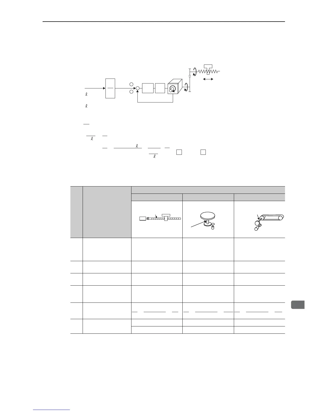
(3) Electronic Gear Ratio Equation
Refer to the following equation to determine the electric gear ratio.
(4) Electronic Gear Ratio Setting Examples
The following examples show electronic gear ratio settings for different load configurations.
A
B
m
n
+
−
Pitch = P (mm/rev)
m
n
Servomotor
P
G
P/rev
P
G
P/revޓ㧦Encoder resolution
Position
loop
Speed
loop
Reference pulse
Δ
n × P
n × P
B
Δ
A
Δ
P
Δ
Δ
×
×
()
m
n
= P
G
× m
B
A
()
==
P
G
× m × P
G
Set A and B with the following parameters.
A
㧦Pn20E
B
㧦Pn210
P mm/rev㧦Ball screw pitch
: Gear ratio (m is the rotation of the motor and n is the rotation of the load shaft.)
mm/P 㧦Reference unit
mm/P
Step Operation
Load Configuration
Ball Screw Disc Table Belt and Pulley
1
Check machine specifica-
tions.
x Ball screw pitch: 6 mm
x Gear ratio: 1/1
Rotation angle per revolu-
tion: 360°
Gear ratio: 1/100
Pulley diameter: 100 mm
(pulley circumference: 314
mm)
• Gear ratio: 1/50
2
Check the encoder reso-
lution.
1048576 (20-bit) 1048576 (20-bit) 1048576 (20-bit)
3
Determine the reference
unit used.
Reference unit: 0.001 mm
(1 μm)
Reference unit: 0.01°
Reference unit: 0.005 mm
(5 μm)
4
Calculate the travel dis-
tance per load shaft revo-
lution.
6 mm/0.001 mm=6000 360°/0.01°=36000 314 mm/0.005 mm=62800
5
Calculate the electronic
gear ratio.
6 Set parameters.
Pn20E: 1048576 Pn20E: 104857600 Pn20E: 52428800
Pn210: 6000 Pn210: 36000 Pn210: 62800
Ball screw
pitch: 6 mm
20-bit encoder
Load shaft
Reference unit: 0.001 mm
20-bit encoder
Load shaft
Reference unit: 0.01°
Gear ratio:
1/100
Load shaft
Gear ratio
1/50
Reference unit: 0.005 mm
Pulley diameter:
100 mm
20-bit encoder