5-50
Note Attach a Momentary Power Interruption Compensation Unit if compensation for power interruptions of up to 2.0 seconds is required for 200 V class
Inverters with outputs of 0.4 to 11 kW.
* If C6-02 is set to 0, 1, or F and the initial value of C6-03 and C6-04 is 2.0 kHz, the initial settings for C6-02 are as follows: 2: 5.0 kHz, 3: 8.0 kHz,
4: 10 kHz, 5: 12.5 kHz, and 6: 15 kHz. If the carrier frequency is set higher than the factory setting for Inverters with outputs of 30 kW or more, the
Inverter rated current will need to be reduced.
Con-
stant
Number
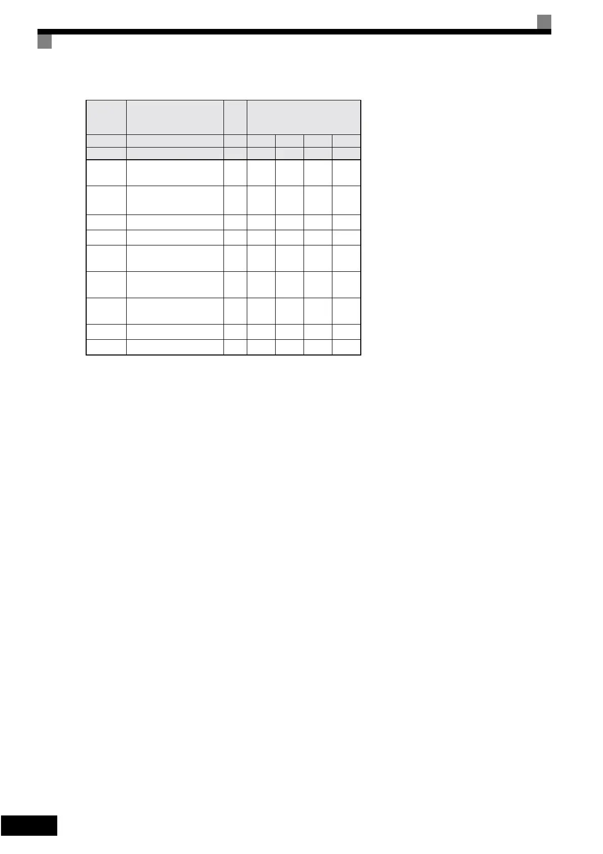
Name Unit Factory Setting
– Inverter Capacity kW 160 185 220 300
o2-04 kVA selection – 34 35 36 37
b8-04
Energy-saving coeffi-
cient
–
30.13 30.57 27.13 21.76
C6-02
Carrier frequency selec-
tion
*
–2211
E2-01 Motor rated current A
270.0 310.0 370.0 500.0
E2-03 Motor no-load current A
70.0 81.0 96.0 130.0
E2-05
Motor line-to-line resis-
tance
Ω
0.029 0.025 0.020 0.014
L2-02
Momentary power loss
ridethru time
s2.02.02.02.0
L2-03
Min. baseblock (BB)
time
s1.81.92.02.1
L2-04 Voltage recovery time s 1.0 1.0 1.0 1.0
L8-02 Overheat pre-alarm level °C 108 95 100 108
Artisan Technology Group - Quality Instrumentation ... Guaranteed | (888) 88-SOURCE | www.artisantg.com