User Constant Tables
5-33
E: Motor Constant Constants
The following settings are made with the motor constant constants (E constants): V/f characteristics and motor
constants.
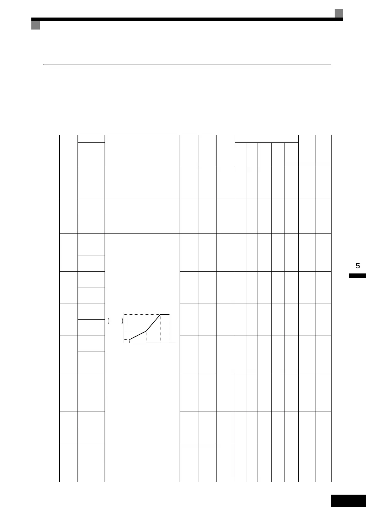
V/f Pattern: E1
User constants for V/f characteristics are shown in the following table.
Con-
stant
Num-
ber
Name
Description
Setting
Range
Factory
Setting
Change
during
Opera-
tion
Control Methods
MEMO-
BUS
Regis-
ter
Page
Display
V/f
V/f
with
PG
Open
Loop
Vec-
tor
1
Flux
Vec-
tor
Open
Loop
Vec-
tor
2
E1-01
Input volt-
age setting
Set the Inverter input voltage in 1
volt.
This setting is used as a reference
value in protection functions.
155 to
255
*1
200 V
*1
NoQQQQQ300H
4-5
6-120
Input Volt-
age
E1-03
V/f pattern
selection
0 to E: Select from the 15 preset
patterns.
F: Custom user-set patterns
(Applicable for settings E1-04
to E1-10.)
0 to F F No Q Q No No No 302H 6-120
V/F Selec-
tion
E1-04
Max.
output
frequency
To set V/f characteristics in a
straight line, set the same values for
E1-07 and E1-09. In this case, the
setting for E1-08 will be disre-
garded.
Always ensure that the four fre-
quencies are set in the following
manner:
E1-04 (FMAX) ≥ E1-06 (FA) > E1-
07 (FB) ≥ E1-09 (FMIN)
40.0 to
400.0
*5
60.0
Hz
*2
No Q Q Q Q Q 303H 6-120
Max
Frequency
E1-05
Max.
voltage
0.0 to
255.0
*1
200.0
V
*1*2
No Q Q Q Q Q 304H 6-120
Max
Vo lt a g e
E1-06
Base
frequency
0.0 to
400.0
*5
60.0
Hz
*2
No Q Q Q Q Q 305H 6-120
Base
Frequency
E1-07
Mid. output
frequency
0.0 to
400.0
3.0 Hz
*2
No A A A No No 306H 6-120
Mid
Frequency
A
E1-08
Mid. output
frequency
voltage
0.0 to
255.0
*1
11.0 V
*1 *2
No A A A No No 307H
4-18
6-120
Mid
Vo l t a g e A
E1-09
Min. output
frequency
0.0 to
400.0
*5
0.5 Hz
*2
No Q Q Q A Q 308H 6-120
Min
Frequency
E1-10
Min. output
frequency
voltage
0.0 to
255.0
*1
2.0 V
*1 *2
No A A A No No 309H
4-18
6-120
Min
Vo lt a g e
Output voltage (V)
Frequency (Hz)
VMAX
(E1-05)
(V BASE)
(E1-13)
VC
(E1-08)
VMIN
(E1-10)
FMIN
(E1-09)
FB
(E1-07)
FA
(E1-06)
FMAX
(E1-04)