2-22
Wiring Control Circuit Terminals
Wire Sizes and Closed-loop Connectors
For remote operation using analog signals, keep the control line length between the Digital Operator or opera-
tion signals and the Inverter to 50 m or less, and separate the lines from high-power lines (main circuits or
relay sequence circuits) to reduce induction from peripheral devices.
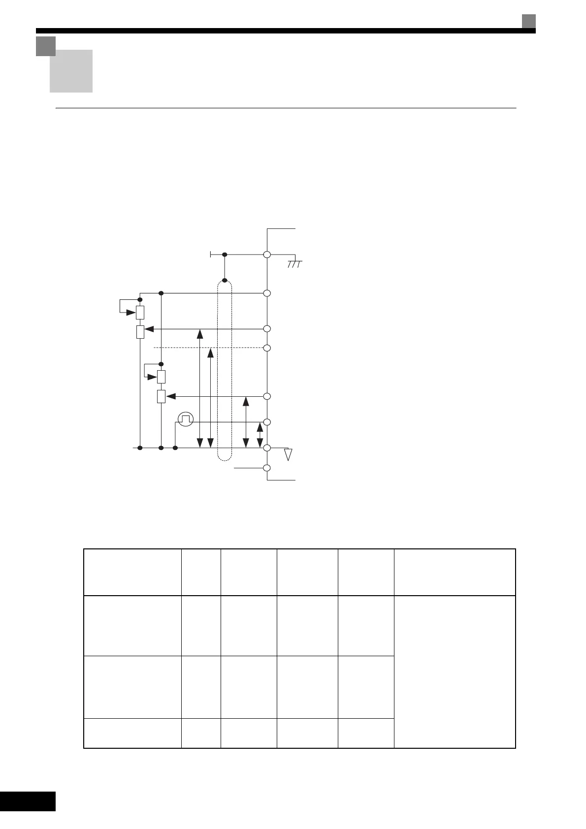
When setting frequencies from an external frequency setter (and not from a Digital Operator), use shielded
twisted-pair wires and ground the shield to terminal E (G), as shown in the following diagram.
Fig 2.14
Terminal numbers and wire sizes are shown in Tabl e 2.9 .
* 1. Use shielded twisted-pair cables to input an external frequency reference.
* 2. Refer to Table 2.3 Closed-loop Connector Sizes (JIS C2805) (200 V Class and 400 V Class) for suitable closed-loop crimp terminal sizes for the wires.
* 3. We recommend using straight solderless terminal on signal lines to simplify wiring and improve reliability.
Table 2.9 Terminal Numbers and Wire Sizes (Same for all Models)
Te rm ina ls
Te rm i-
nal
Screws
Tightening
Torque
(N•m)
Possible Wire
Sizes
mm
2
(AWG)
Recom-
mended
Wire Size
mm
2
(AWG)
Wire Type
FM, AC, AM, P1, P2,
PC, SC, A1, A2, A3, +V,
-V, S1, S2, S3, S4, S5, S6,
S7, S8, MA, MB, MC,
M1, M2
M3.5 0.8 to 1.0
0.5 to 2
*2
(20 to 14)
0.75
(18)
• Shielded, twisted-pair wire
*1
• Shielded, polyethylene-cov-
ered, vinyl sheath cable
(KPEV-S by Hitachi Electri-
cal Wire or equivalent)
P3, C3, P4, C4, MP, RP,
R+, R-, S9, S10, S11,
S12, S+, S-, IG
Phoenix
type
0.5 to 0.6
Single wire
*3
:
0.14 to 2.5
Stranded wire:
0.14 to 1.5
(26 to 14)
0.75
(18)
E (G) M3.5 0.8 to 1.0
0.5 to 2
*2
(20 to 14)
1.25
(12)
P
P
P
P
E(G)
Shield terminal
㧗V Speed setting power supply, +15 V 20 mA
A1 Master speed reference 0 to 10 V (-10 to 10 V)
A2 Master speed reference 4 to 20 㨙A
(0 to 10 V, -10 to 10 V)
A3 Auxiliary reference 0 to 10 V (-10 to 10 V)
RP Pulse train input 32 kHz max.
AC Analog common
2kΩ
2kΩ
2kΩ
2kΩ
-V Speed setting power supply -15 V 20 mA