6-56
• Undertorque Detection
Changing Overtorque and Undertorque Detection Levels Using an Ana-
log Input
If you set constant H3-09 (Multi-function Analog Input Terminal A2 Function Selection) or H3-05 (Multi-
function Analog Input Terminal A3 Function Selection) to 7 (overtorque/undertorque detection level), you can
change the overtorque/undertorque detection level.
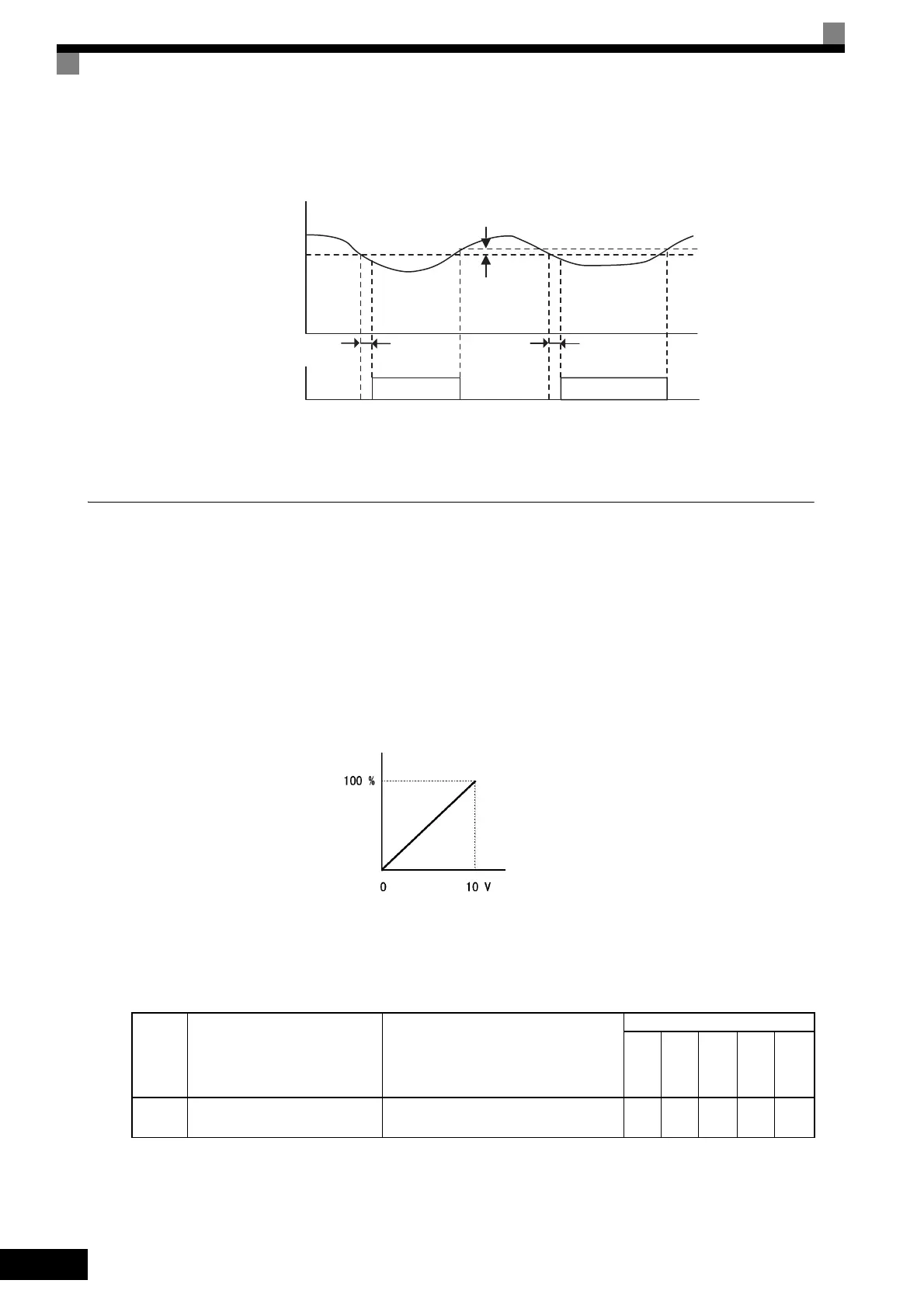
If you change the overtorque/undertorque detection level using the multi-function analog input, only over-
torque/undertorque detection level 1 will be enabled.
The following diagram shows the overtorque/undertorque detection level using an analog input.
Fig 6.40 Overtorque/Undertorque Detection Level Using an Analog Input
Multi-Function Analog Input (H3-05, H3-09)
Set-
ting
Value
Function Contents (100%)
Control Methods
V/f
V/f
with
PG
Open
Loop
Vec-
tor
1
Flux
Vec-
tor
Open
Loop
Vec-
tor
2
7
Overtorque/undertorque detection
level
Motor rated torque for vector control
Inverter rated output current for V/f control
Yes Yes Ye s Yes Ye s
Motor current (output torque)
Undertorque detection 1 NO
or Undertorque detection 2 NO
L6-03
or
L6-06
L6-03
or
L6-06
* The undertorque detection disabled margin is approximately 10% of the Inverter rated output
current (or motor rated torque)
L6-02 or L6-05
*
ON ON
Detection level
Multi-function analog input
terminal A2, A3 input level
(4 mA)
(20 mA)