6-146
Multi-function Contact Input Functions (H1-01 to H1-10)
Multi-function Contact Output Functions (H2-01 to H2-05)
To output the zero-servo status externally, assign the Zero-servo End signal (setting 33) to one of the multi-
function outputs (H2-01 to H2-05).
Monitor Function
Time Chart
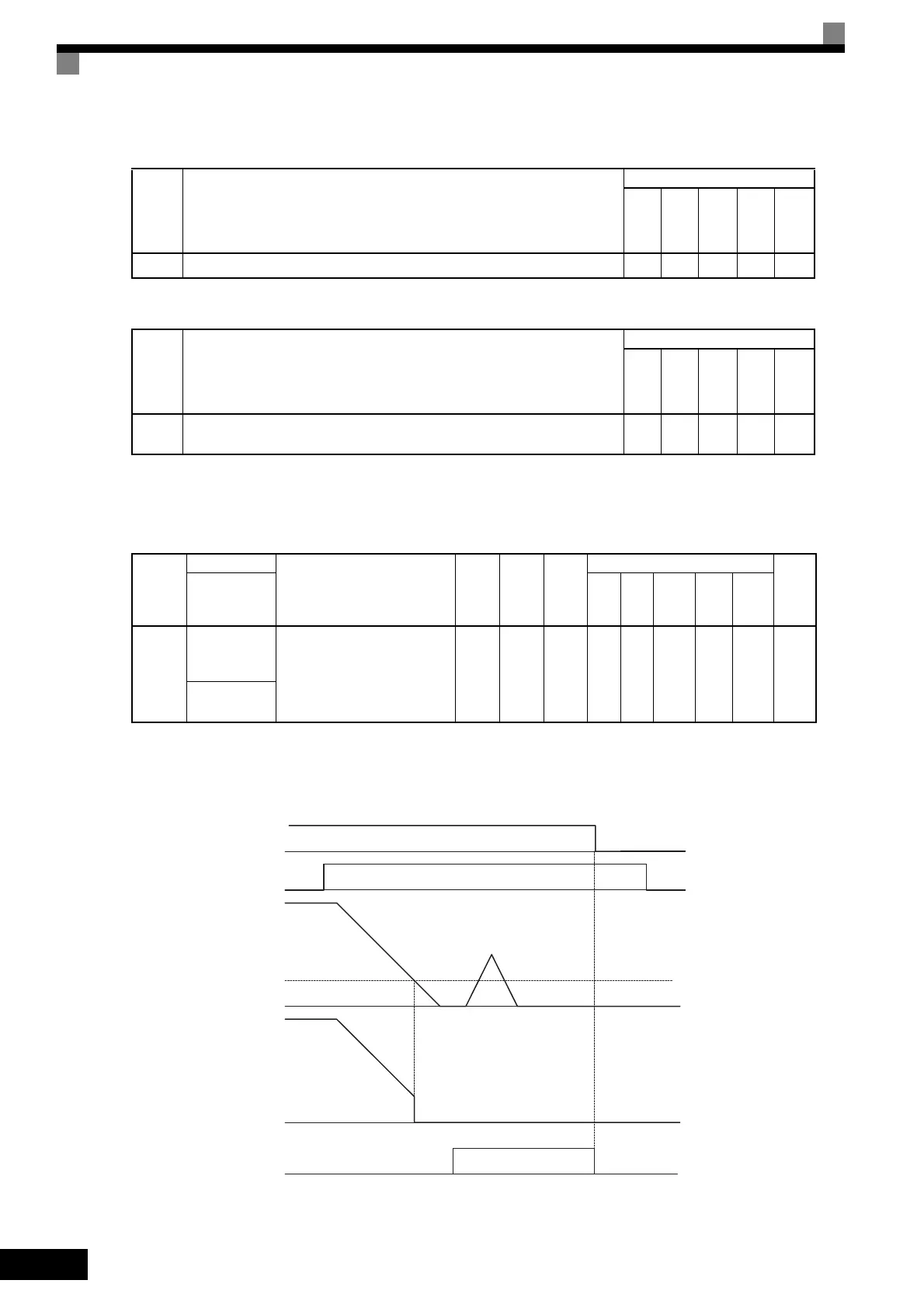
A time chart for the zero-servo function is given in Time Chart for Zero-servo.
Fig 6.81 Time Chart for Zero-servo
Set-
ting
Value
Function
Control Methods
V/f
V/f
with
PG
Open
Loop
Vec-
tor
1
Flux
Vec-
tor
Open
Loop
Vec-
tor
2
72 Zero-servo command (ON: Zero-servo) No No No Yes No
Set-
ting
Value
Function
Control Methods
V/f
V/f
with
PG
Open
Loop
Vec-
tor
1
Flux
Vec-
tor
Open
Loop
Vec-
tor
2
33
Zero-servo end
ON: Current position is within zero-servo start position ± the zero-servo end width.
No No No Yes No
Con-
stant
Number
Name
Description
Setting
Range
Factory
Setting
Change
during
Opera-
tion
Control Methods
MEMO
BUS
Regis-
ter
Display
V/f
V/f
with
PG
Open
Loop
Vector
1
Flux
Vec-
tor
Open
Loop
Vector
2
U1-35
Zero-servo
movement
pulses
Shows the number of PG pulses
times 4 for the movement range
when stopped at zero.
(Can-
not be
out-
put.)
1 No No No A No 62H
Zero Servo
Pulse
Run Command
ON OFF
Zero servo command
Frequency (speed) reference
Excitation level
b2-01
Motor speed
Zero Servo End signal Zero-servo status
ON OFF
 Loading...


