4
All Rights Reserved. Copyright © 2014, Yokogawa Electric Corporation
GS 04L53B01-01EN Nov. 10, 2015-00
• Burnout detection: Burnout upscale, downscale,
orOFFselectable(foreachchannel).
Availableinput:TC,RTD,Standardsignal
Detection condition;
TC;Normal:2kΩorless.,Burnout:200kΩor
more(parallelcapacitanceof0.01μForless)
Detectioncurrent:Approx.10μA
RTD;Normal:wiringresistanceorless,
Burnout:200kΩormore
parallelcapacitanceoflessthan0.01μFor
less
Detectioncurrent:Approx.10μA
Standard signal:
Normal:Withinmeasuringrange
Burnout: Depends on the setting of the
burnoutjudgmentvalue.Theburnout
judgmentvalueshallbesetwiththe
percentageofthespeciedspanwidth.
Lowerlimit:-20.0to-5.0%
Upperlimit:105to120%
• Input external resistance:
DCvoltage,thermocoupleinput:2kΩorbelow
Resistancetemperaturedetectorinput:10Ω
orbelowineachwire(Sameresistancein
three wires)
• Input bias current: ±10 nA or less (when burnout
function does not work)
• Measuredcurrent(forRTD):Approx.1mA
• Input resistance:
10MΩormoreforTC/DCvoltage(1Vrangeor
less) input
Approx.1MΩforDCvoltage(2Vrangeor
more)/standardsignalinput
250Ω(249.5Ωtyp)forDCmA
*typ:Typicalvalue(Typical)
• Allowablesignalsourceresistance:2kΩorless
forTC/DCvoltage(1Vrangeorless)input
• Effect of signal source resistance:
±10μV/1kΩorlessforTC/DCvoltage(1Vrange
or less) input
±0.15%/1kΩorlessforDCvoltage(2Vrangeor
more)/standardsignalinput
• Allowablewiringresistance:Max.10Ωperline
forRTDinput(conductorresistancebetweenthe
threelinesshallbeequal)
• Effectofwiringresistance:±0.1°C/10ΩforRTD
input (conductor resistance between the three
linesshallbeequal)
• Allowable input voltage:
±10VDCforTC/DCvoltage(1Vrangeorless)/
RTD/DIinput,DCmA
±60VDCforDCvoltage(2Vrangeormore)input
• Allowable input current (current scanner type):
24mA,50/60Hz,peakvalueincludingsignal
• Noise reduction ratio
Integration time
*1
Normal mode Common mode
1.67ms 50/60 Hz, no
noise reduction
More than 80 dB
*2
*4
More than 16.67
ms
More than 40 dB
*2
*3
More than 120 dB
*2
*4
*1 Afrequencydiscriminationsettingismadeinthe
mainunit.
*2
Aresistancetemperaturedetectorrangeisaconverted
valueofvoltagewhenameasuredcurrentows.
*3 50/60Hz±0.1%
*4 50/60Hz±0.1%,500Ωimbalance,between
minusmeasuringterminalandground
• NormalmodevoltageforTC/DCvoltage(1V
rangeorless)/DI(voltage):1.2timesorlessof
rated range
Standardsignal0.4to2Vrange:2.4V
Standardsignal1-5Vrange:6V
RTD(100Ω):50mVpeak
RTD(50Ω):10mVpeak
* 50/60Hz,Thepeakvalueincludingthesignal.
• Normalmodecurrent(current,scannertype):24
mADC(Valueconvertedtovoltage:6V)
*50/60Hz,Thepeakvalueincludingthesignal.
• Commonmodevoltageformeasuringinput:
30VACrms(50/60Hz)or±60VDC(Maximum
commonmodenoisevoltageformeasuring
input:250VACrms)
• Maximumvoltagebetweenmeasuringinput
channels:30VACrms(50/60Hz)or±60VDC
(Maximumcommonmodenoisevoltagebetween
measuringinputchannels:250VACrms(60V
ACrmsforlow-voltagerelaytype)
• Referencejunctioncompensationaccuracy:
Whenmeasuringtemperaturegreaterthan
orequalto0°Candwheninputterminal
temperatureisbalanced
Type K, E, J, T, N, XK GOST: ±0.5 °C (23 °C ± 2
°C), ±0.7 °C (0 to 50 °C), ±1.0 °C (-20 to 60 °C)
TypeR,S,W,L,U,W97Re3-W75Re25,
Platinel2,NiNiMo,W/WRe26,N(AWG14):±1.0
°C (23 °C ± 2 °C), ±1.4 °C (0 to 50 °C), ±2.0 °C
(-20 to 60 °C)
TypeKpvsAu7Fe:±1.0K(23°C±2°C),±1.4K
(0 to 50 °C), ±2.0 K (-20 to 60 °C)
TypeB,PR20-40:Internalreference
compensationisxedto0°C
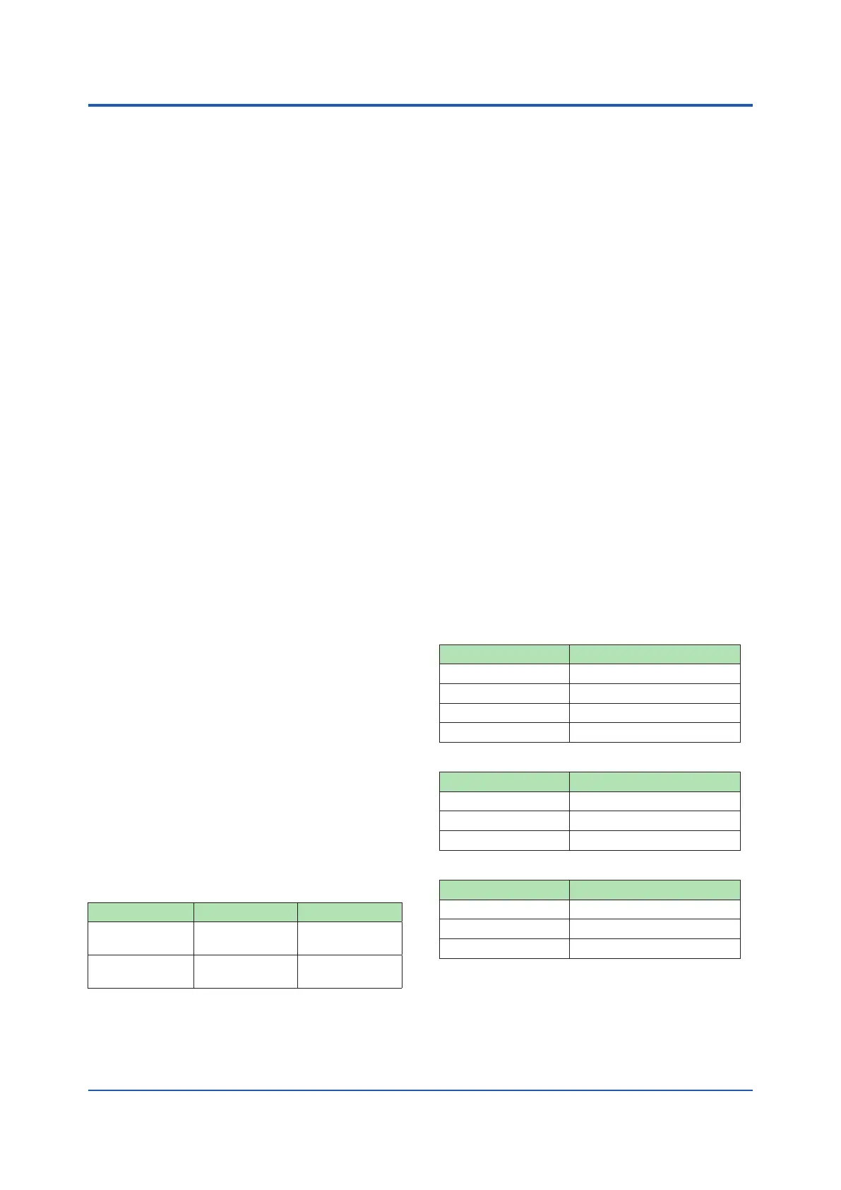
• Samplinginterval/A/Dintegrationtime:
10ch.mode
Universal(-U2)
*1
/ Current scanner type (-C1)
*1
Sampling interval Integration time
100ms/200ms 1.67ms
500msormore 16.67ms/20ms
1 s 36.67ms
2sormore 100ms
Electromagneticrelayscannertype(-T1)
Sampling interval Integration time
1sormore 16.67ms/20ms
2 s 36.67ms
5 s 100ms
Scannertype(DCV/TC/DI,400VAC,1min)(-L1)
Sampling interval Integration time
500msormore 16.67ms/20ms
2 s 36.67ms
5 s 100ms
 Loading...