INSTALLATION INSTRUCTIONS AND FIRST-TIME SET-UP
Axio Observer Reflector turret ZEISS
12/2016 431004-7244-001 57
If you need to insert filters which have no direction
indicator (arrow), we recommend proceeding as
follows:
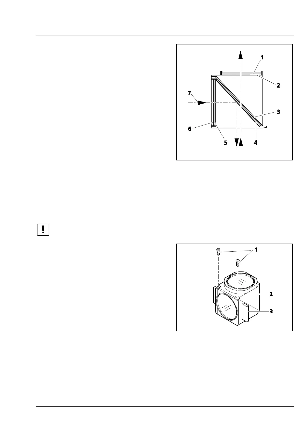
Insert the filters with reflective dielectric coatings
so that the reflective coating (Fig. 37/6) of the
excitation filter (Fig. 37/5) faces outward (relative
to the reflector module). On the barrier filter
(Fig. 37/1), the reflective coating (Fig. 37/2) should
face inward (Fig. 37).
The reflective coating (Fig. 37/4) of the beam
splitter (Fig. 37/3) should face downward when
fitted.
The arrows (Fig. 37/7) mark the illumination and
imaging beam path.
4.11.4 Changing the beam splitter in reflector module FL P&C
Fitting the filters and the beam splitter requires utmost
care to prevent damage to and
contamination of the optical components.
We recommend ordering fully equipped reflector
modules FL P&C, since changing the beam splitter
requires considerable skill.
If you have to change the beam splitter, proceed as
follows:
• Remove the reflector module FL P&C from the
reflector turret (also refer to section 4.11.2).
• Loosen both slotted screws (Fig. 38/1) using a
screwdriver.
• Hold both halves of the reflector module
together (emission half (Fig. 38/2) and
excitation half (Fig. 38/3), turn them in the
position opposite to the installation position
and put them down.
Fig. 37 Inserting the filters and the beam
splitter
Fig. 38 Changing the beam splitter