INSTALLATION INSTRUCTIONS AND FIRST-TIME SET-UP
ZEISS Reflector turret Axio Observer
58 431004-7244-001 12/2016
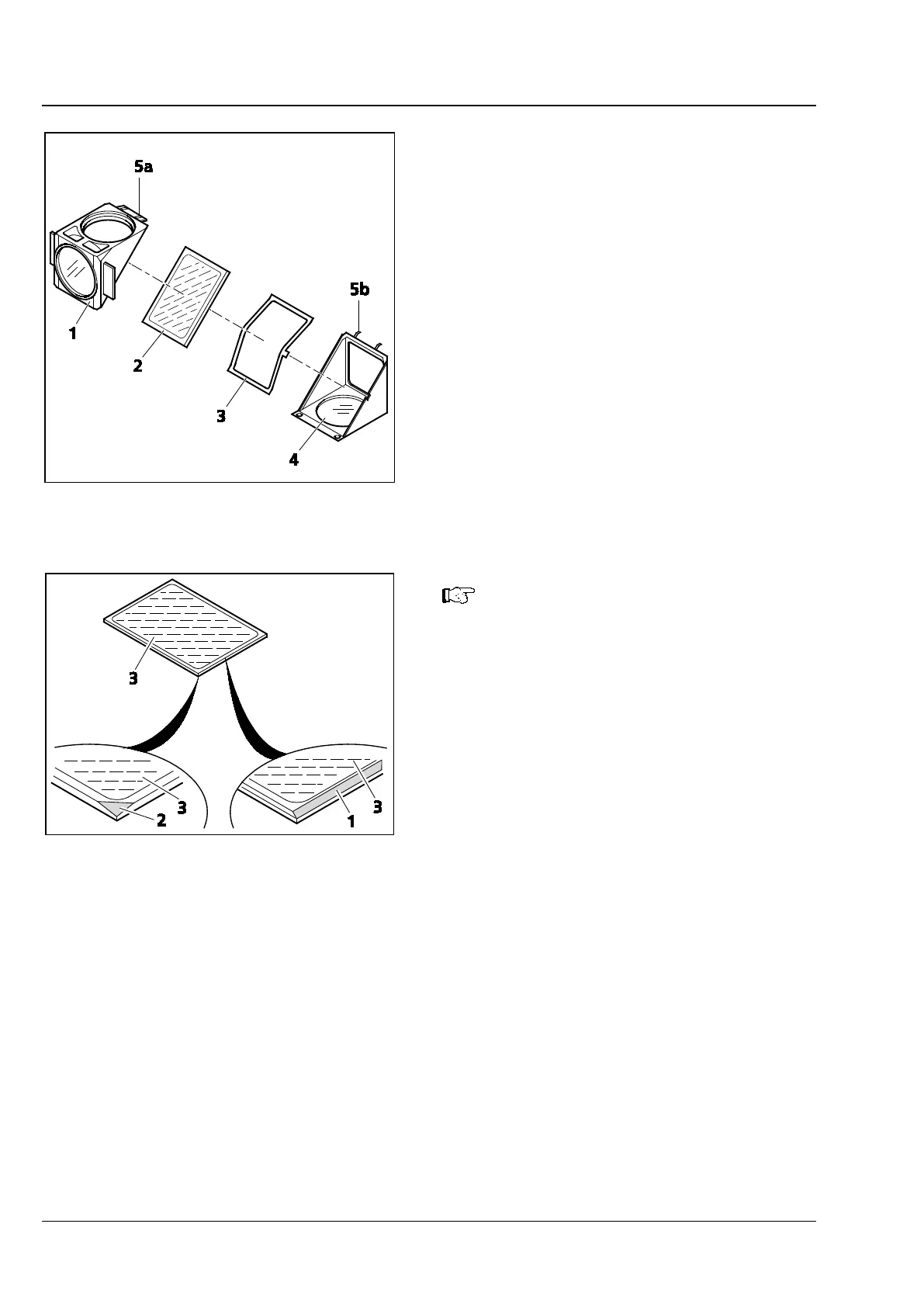
• Tilt up the excitation half (Fig. 38/1), which
now is on top, and remove it from the retaining
elements (Fig. 38/5b) of the lower half
(emission) (Fig. 38/4).
• Remove beam splitter (Fig. 38/2) and spring-
loaded frame (Fig. 38/3) from the lower half of
the module.
• Remove the old beam splitter and carefully
place the new one on the spring-loaded frame
(Fig. 38/3) with the reflecting side facing up and
place both parts together into the lower half of
the module. Ensure that the catch on the side
of the spring-loaded frame is positioned in the
recess in the lower half of the module.
The reflective (coated) side (Fig. 40
/3)
of the beam splitter has a beveled
edge (Fig. 40/1) or corner (Fig. 40/2).
• Place the excitation half of the module
(Fig. 38/1) on top of the emission half
(Fig. 38/4) (retaining elements Fig. 38/5b
engage with eyelets Fig. 38/5a). Holding the
two halves together, turn the module back into
the position for insertion.
• Reinsert the slotted screws and screw tight.
• Finally, attach the adhesive label with the name
of the filter combination to the side of the
module.
Fig. 39 Changing the beam splitter
Fig. 40 Labeling on the beam splitter