Axiotech and Axiotech
vario
Carl Zeiss
B 40-020 e 06/99 3-27
•
Set optimum polarization image by turning the specimen (turn the specimen itself when the fixed
mechanical stage is used, or the stage when using the rotary mechanical stage!).
•
If required, the compensator DIC lambda or Pol lambda sub, ± 10° (3-24/10) can also be inserted into
the reflector slider HD DIC from the right, and the adjusting lever of the latter can be used to optimize
the contrast.
3.4.8.3
Transmitted light polarization contrast using reflector slider without DIC position on
the Axiotech 30 and Axiotech 100
☞
Polarization contrast using the reflector slider without DIC position in combination with the
transmitted-light equipment is possible with the ± 10° rotary analyzer slider, Cat. No. 453686-
0000-000.
•
Perform steps described in sections 2.13.1,
2.13.2 and 3.3.
•
Place the specimen to be examined on the
microscope stage and fix it.
•
Use the lower lever (3-23/15) to swing polarizer
D (3-23/13) into the beam path of the
condenser module, and move the upper lever
(3-23/14) into the zero position until stop (the
upper lever will then point to the front).
•
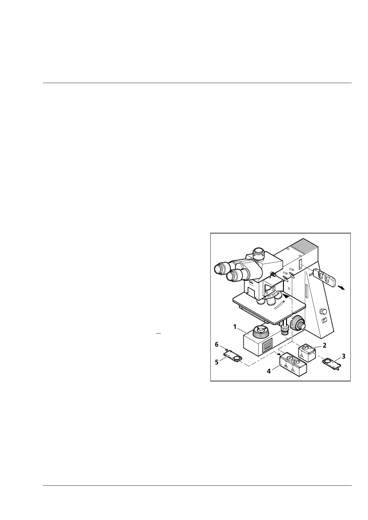
Push HD reflector slider ( 3-25/4) into the
reflected-light illuminator until the H position is
active (H mark visible on the reflector slider).
Insert the ± 10° rotary analyzer slider ( 3-25/5)
into the left mount of the HD reflector slider
until stop. The adjusting lever ( 3-25/6) of the ±
10° rotary analyzer slider permits the image
contrast to be further optimized with crossed
polars.
•
The Pol reflector slider ( 3-25/2), which can be
used as an alternative, features an integrated
analyzer in the function position and can
therefore also be equipped with the
compensator DIC lambda or Pol lambda sub ±
10° (3-25/3). Since no beam splitter is required,
the Pol reflector slider has the additional benefit
of an intensity gain of about 50%.
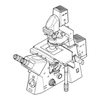
Fig. 3-25 Setting of transmitted-light
polarization contrast using reflector
slider without DIC position
(Axiotech 30/100)



 To Next Page