14
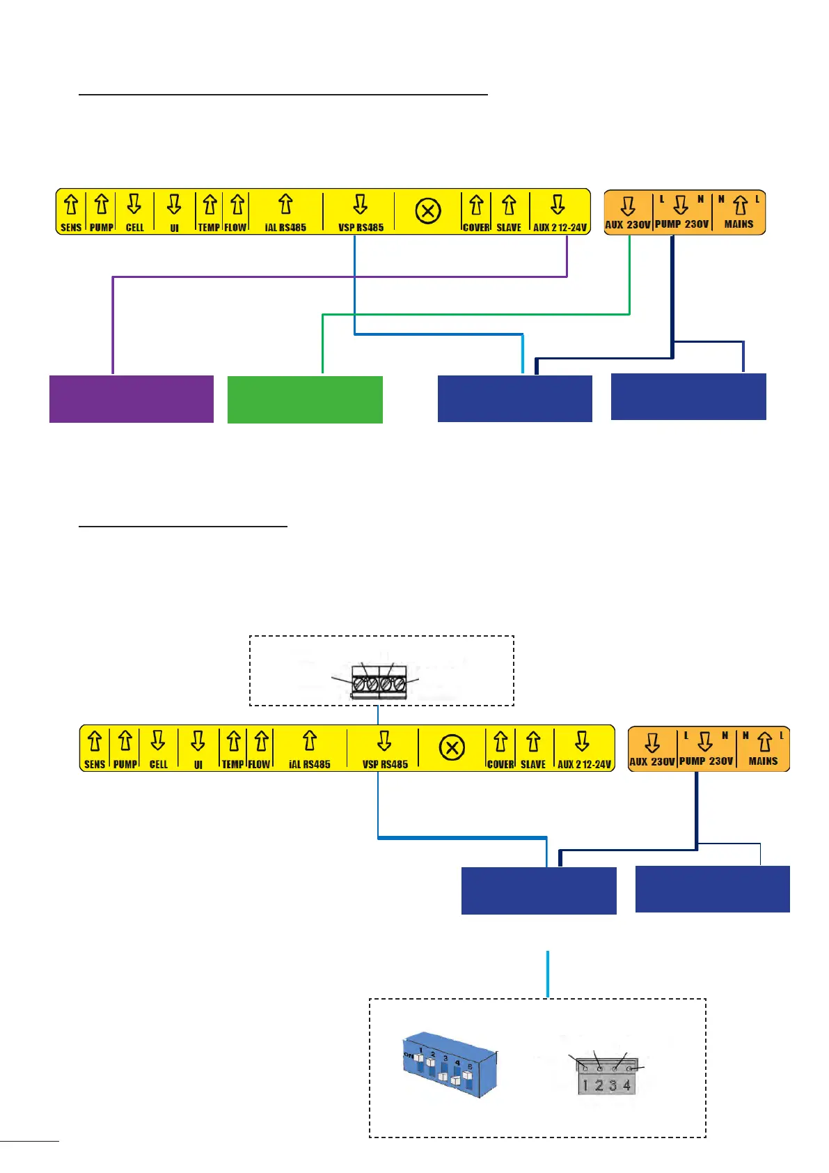
2.5.4 External connecons: what products should be connected?
The chlorinator must be protected by a circuit breaker of the same type as that used for a lter pump (for
example a ltraon control panel).
If the chlorinator is powered by a ltraon control panel, the mers must be manually set to 24/7 mode. The
chlorinator manages all mers and must receive a connuous power supply.
12 - 24 V contact
230 V contact
RS485 cable (supplied
with the pump)
230 V power
supply
230 V power
supply
All types of auxiliary device
12 - 24 V
All types of auxiliary
device
230 V
FloPro™ VS
All lter pump models
Heang (heat pump, heat
exchanger, electric heater),
booster pump, etc.
maximum 8 A
Transformer for lighng,
booster pump, etc.
maximum 8 A
Variable-speed pump
maximum 8 A
Single-speed pump or
variable 3-speed pump of
type FloPro™ e3.
maximum 8 A
2.5.5 Connecng to a lter pump
The chlorinator can power and control the lter pump.
In such a case, the chlorinator must be powered via an electrical protecon that is calibrated for a lter pump.
Possible controls:
- For a single-speed pump (SSP): ON/OFF with 2 mers,
- For a FloPro™ VS variable-speed pump (VSP): ON/OFF/RPM with 4 mers.
(see installaon manual for the Zodiac™
FloPro® VS lter pump)
RS485 Cable
(supplied with the
pump)
Power supply
230 V
230 V power
supply
FloPro™ VS
All lter pump models
Variable-speed pump
maximum 8 A
Single-speed pump for
all models or compable
Zodiac® variable-speed
pump.
maximum 8 A
GREEN
YELLOW
BLACK
RED
RED
BLACK
YELLOW
GREEN
(Terminal block at the level of the FloPro™ VS pump)