GS-4012F User’s Guide
Chapter 3 Hardware Overview 43
CHAPTER 3
Hardware Overview
This chapter describes the front panel and rear panel of the switch and shows you how to make
the hardware connections.
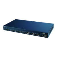
3.1 Front Panel Connection
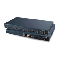
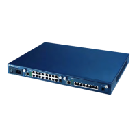
The figure below shows the front panel of the switch.
Figure 9 Front Panel
The following table describes the port labels on the front panel.
3.1.1 Console Port
For local management, you can use a computer with terminal emulation software configured
to the following parameters:
• VT100 terminal emulation
• 9600 bps
• No parity, 8 data bits, 1 stop bit
• No flow control
Connect the male 9-pin end of the console cable to the console port of the switch. Connect the
female end to a serial port (COM1, COM2 or other COM port) of your computer.
Table 1 Front Panel
PORT DESCRIPTION
CONSOLE Only connect this port if you want to configure the switch using the command line
interface (CLI) via the console port.
12 mini-GBIC
slots
Use mini-GBIC transceivers in these slots for fiber-optical connections to backbone
Ethernet switches (see Section 3.1.3 on page 44 for instructions).
Gigabit/mini-
GBIC ports
Connect these Gigabit Ethernet ports to high-bandwidth backbone network Ethernet
switches or use them to daisy-chain other switches.
Alternatively, use mini-GBIC transceivers in these slots for fiber-optical connections to
backbone Ethernet switches.
 Loading...