Network Configuration Examples 19
Suggested Deployment of VLANs
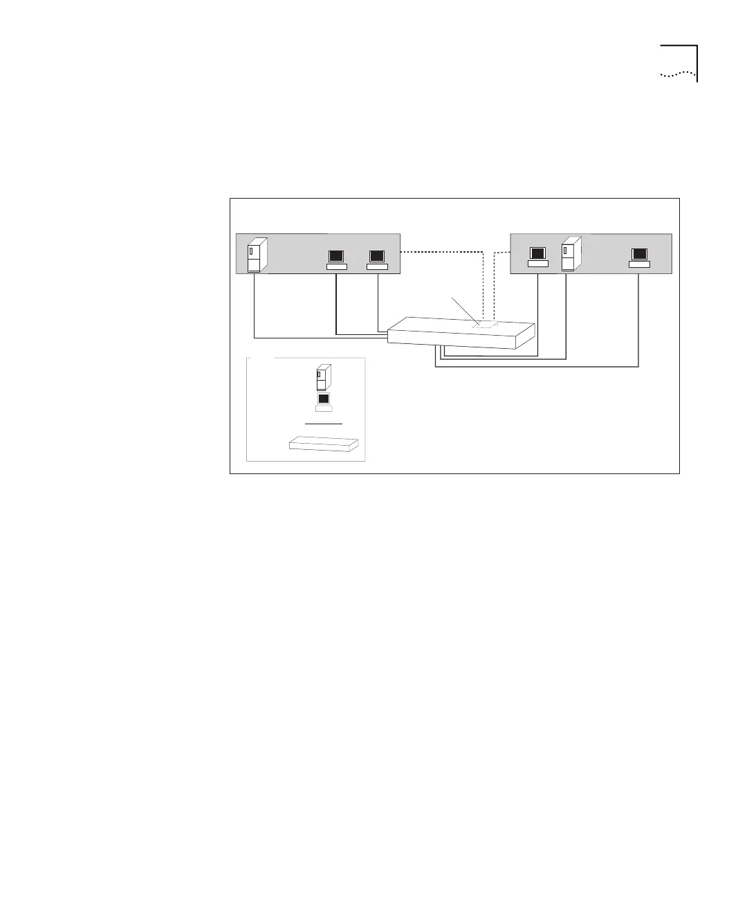
In Figure 2, the same LAN is divided into two VLANs.
Figure 2 Example of VLANs Used in the Simple Network
The addition of VLANs means that:
■ Traffic between devices on VLAN 1 is not seen on VLAN 2.
■ Broadcast traffic from hosts on VLAN 1 is not seen on VLAN 2.
However, devices on VLAN 1 and VLAN 2 cannot communicate at
Layer 2.
The addition of the Layer 3 Module in Switch A allows packets to be
routed between VLANs.
Traffic routed
between VLANS
VLAN 1 VLAN 2
Server B in
Engineering
VLAN 2
Layer 3 Module
Server A in
Marketing
VLAN 1
IP Network Address: 192.168.168.128
Subnet Mask: 255.255.255.192
IP Network Address: 192.168.168.64
Subnet Mask: 255.255.255.192
Server
Workstation
Key
Cable
Switch
Switch A