page 5
A10 Thunder Series 6430(S) ADC/CGN
LED Locations and Status Indicators
• 1 Ethernet interface (Mgmt) for remotely managing the device over the network
• 1 Lights Out Management (LOM) interface. This 1 Gbps interface is used for remotely powering
the device on/off or reloading the device over the network. (See the Lights Out Management Refer-
ence Guide for details on configuring this interface.)
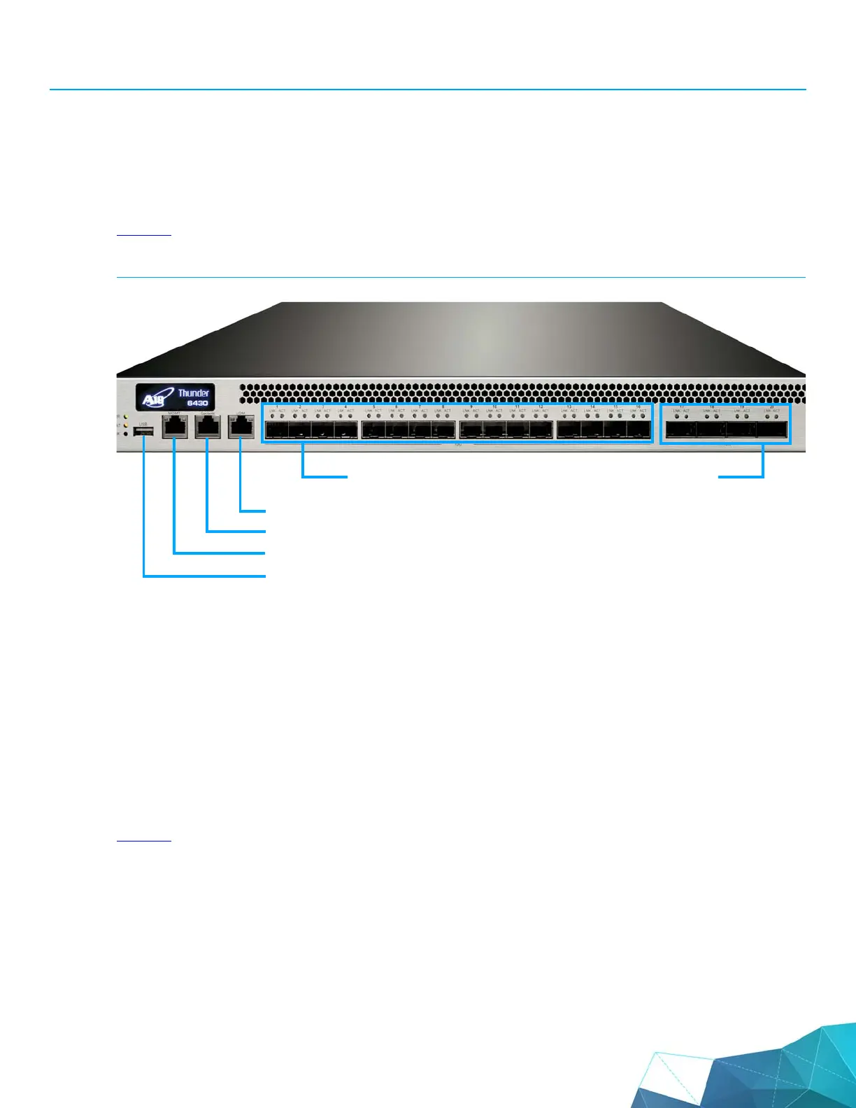
Figure 3
illustrates where these interfaces are located on the device, and their corresponding numbers.
FIGURE 3 A10 Thunder Series 6430(S) Interfaces and Numbers
To begin using these interfaces, connect the appropriate cables:
1. Connect the serial cable to the serial console interface.
2. Connect Ethernet cables to the data interfaces you plan to use.
3. Optionally, connect an Ethernet cable to the MGMT interface.
LED Locations and Status Indicators
Figure 4 illustrates the locations of the LEDs on the device.
#1 #2 #3 #4 #5 #6 #7 #8 #9 #10#11#12 #13#14#15#16
#17 #18 #19 #20
USB
Management
Console
Lights Out Management (LOM)
10 GB Fiber Data Interfaces
40 GB Fiber Data Interfaces