Commissioning
40 265Dx, 265VS IM/265D/V-EN-02
Pos: 15.12 /Übers chriften/1.1/1-s paltig/D - F/Drehung des Gehäus es gegenüber dem Messwer k @ 5\mod_1165484889437_3101. doc @ 50488
6.4 Turning the housing in relation to the measuring equipment
Pos: 15.13 /Inbet riebnahme/Druck/Dr uckmessumformer/ Allgemein/Drehung des Gehäus es gegenüber dem Mess werk @ 2\mod_1149843345046_31 01.doc @ 29138
The electronics housing can be rotated 360 ° and fixed in any position; a stop is provided to
prevent it from rotating past this point.
• To activate this, slacken the housing stop screw on the neck of the housing (hex-head
socket screw SW 2.5) by approx. 1 rotation (do not pull it out) and, once the desired position
has been reached, retighten it until hand-tight.
Pos: 15.14 /Übers chriften/1.1/1-s paltig/M - O/Montage / Demont age der Tasteinheit @ 2\mod_1149843645359_3101.d oc @ 29159
6.5 Installing/Removing the button unit
Pos: 15.15 /Inbet riebnahme/Druck/Dr uckmessumformer/ Allgemein/Montage / Demont age der Tasteinheit @ 2\mod_1149843760359_3101 .doc @ 29180
1. Slacken the screw on the protective cap and move the cap to one side.
2. Using a suitable screwdriver, for example, push the lock bar all the way out of the button
unit.
3. This releases the square nut; remove this from the button unit.
4. Use a Torx screwdriver (size T10) to slacken the fixing screw for the button unit, and then
remove the unit from the electronics housing.
5. If necessary, insert a filler piece and secure it using the screw supplied.
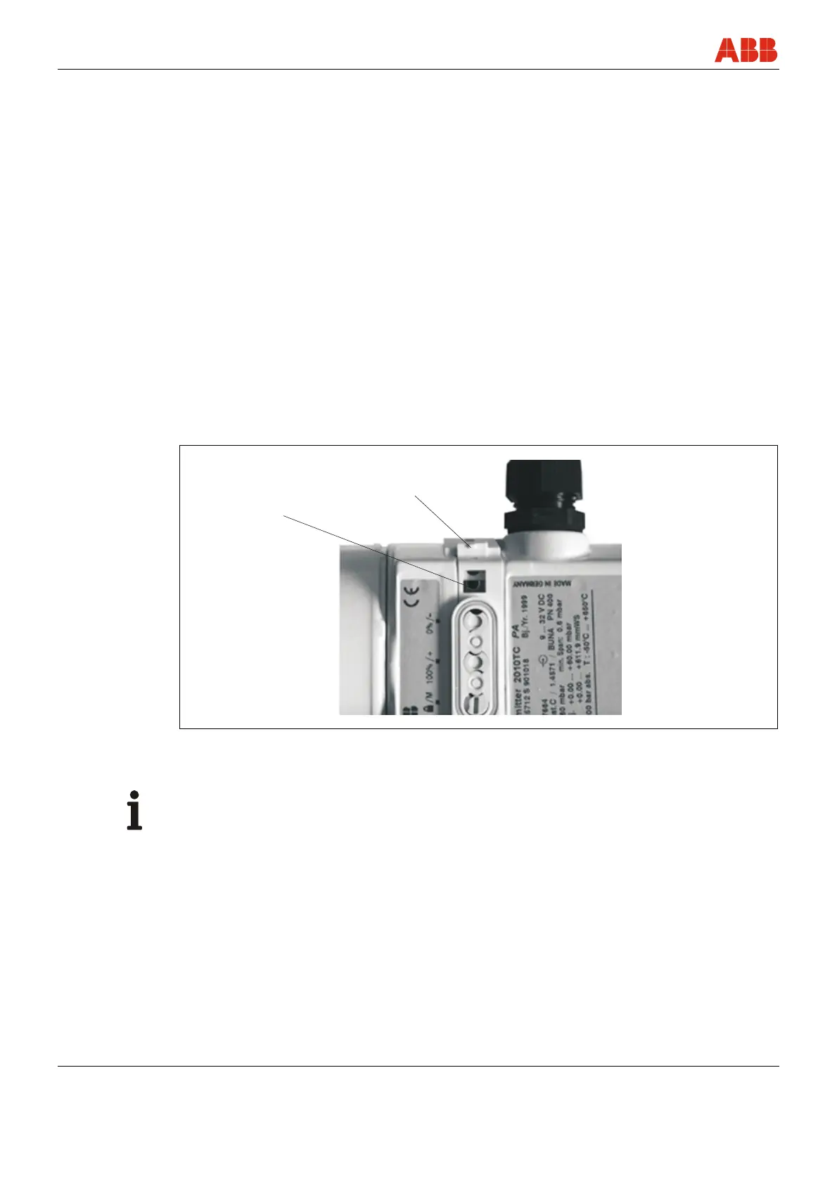
M00042
1
2
Fig. 14: Installing/removing the button unit
1 Fixing screw 2 Lock bar
Important
The fixing screw is located underneath the button unit.
Pos: 15.16 /======= Seitenumbruch ======== @ 0\mod_1126532365768_3101.doc @ 3830