164 Actual signals and parameters
1103
REF1 SELECT
0...32 1 1
Selects the signal source for external reference REF1.
0 = KEYPAD – Defines the control panel as the reference source.
1 = AI1 – Defines analog input 1 (AI1) as the reference source.
2 = AI2 – Defines analog input 2 (AI2) as the reference source.
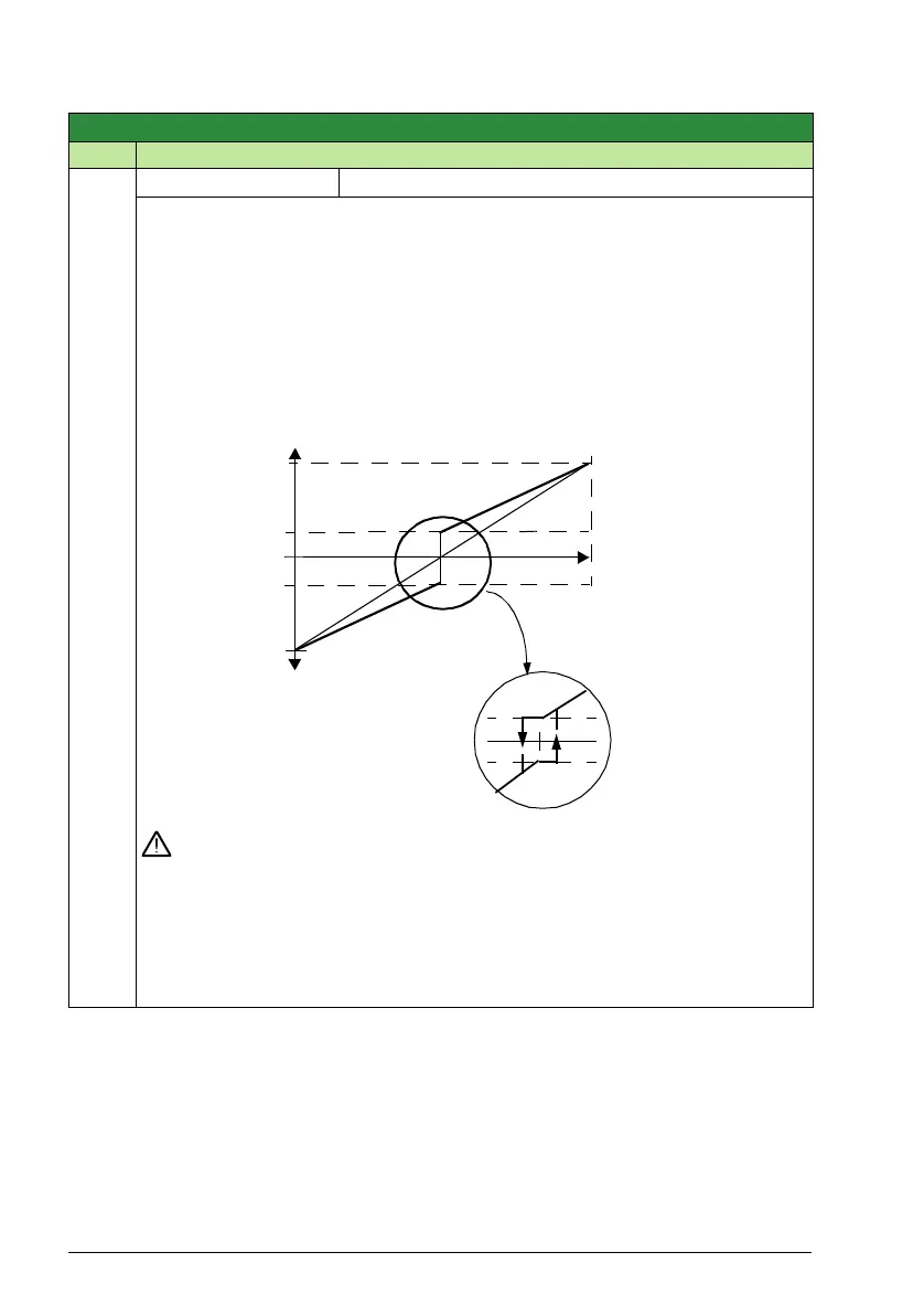
3 = AI1/JOYST – Defines analog input 1 (AI1), configured for joystick operation, as the
reference source.
• The minimum input signal runs the drive at the maximum reference in the reverse
direction. Define the minimum using parameter 1104 REF1 MIN.
• The maximum input signal runs the drive at maximum reference in the forward
direction. Define the maximum using parameter 1105 REF1 MAX.
• Requires parameter 1103 = 3 (request).
WARNING! Because the low end of the reference range commands full reverse
operation, do not use 0 V as the lower end of the reference range. Doing so
means that if the control signal is lost (which is a 0 V input) the result is full reverse
operation. Instead, use the following set-up so that loss of the analog input triggers a
fault, stopping the drive:
• Set parameter 1301 MINIMUM AI1 (1304 MINIMUM AI2) at 20% (2 V or 4 mA).
• Set parameter 3021 AI1 FAULT LIMIT to a value 5% or higher.
• Set parameter 3001 AI<MIN FUNCTION to 1 (FAULT).
Group 11: Reference select
Code Description Range Resolution Default S
+2 %-2 %
10 V /
H
YSTERESIS 4% OF FULL SCALE
EXT
REF 1 MIN
- EXT REF 1 MIN
- EXT REF 1 MAX
EXT
REF 1 MIN
EXT
REF 1 MAX
- EXT REF 1 MIN
2 V / 4 MA
0 V / 0
MA
20 MA