200 Actual signals and parameters
2606
SWITCHING FREQ
1, 4, 8, 12, 16 kHz - 4 kHz
Defines the switching frequency of the drive. Higher switching frequency results in
lower acoustic noise in the motor. See also parameter 2207 SWITCH FREQ CTRL
and section Switching frequency derating, I2N and ILD (= all currents) on page 387.
In multimotor systems, do not change the switching frequency from the default value.
2607
SWITCH FREQ
CTRL
1, 2 - 1
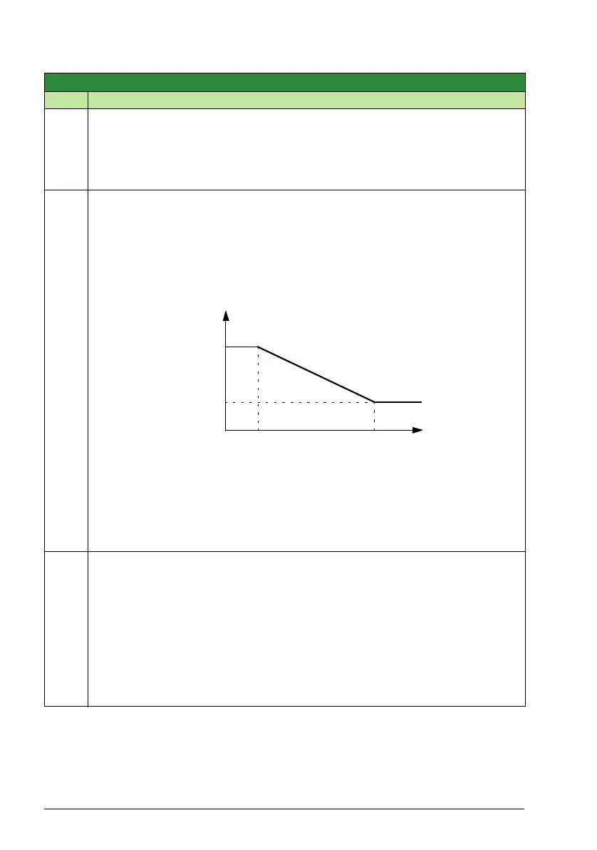
Activates the switching frequency control. When active, the selection of parameter
2606 SWITCHING FREQ is limited when the drive internal temperature increases.
See the figure below. This function allows the highest possible switching frequency at
a specific operation point.
Higher switching frequency results in lower acoustic noise in the motor, but higher
internal losses.
1 = ON – Active.
2 = ON (LOAD) – Switching frequency can adapt to loading instead of limiting the
output current. This allows maximum loading with all switching frequency
selections. The drive automatically decreases the actual switching frequency if
loading is too high for the selected switching frequency.
2608
SLIP COMP RATIO
0 … 200% 1 0
Defines the slip gain for the motor slip compensation control. 100% means full slip
compensation, 0% means no slip compensation. Other values can be used if a static
speed error is detected despite the full slip compensation.
Example: 35 Hz constant speed reference is given to the drive. Despite the full slip
compensation (SLIP COMP RATIO = 100%), a manual tachometer measurement
from the motor axis gives a speed value of 34 Hz. The static speed error is 35 Hz - 34
Hz = 1 Hz. To compensate the error, the slip gain should be increased.
0 = No slip compensation.
1…200 = Slip gain.
Group 26: Motor control
Code Description Range Resolution Default S
* Temperature depends on the drive output frequency.
16 kHz
4kHz
Drive
temperature
f
sw
limit
80…100 °C * 100…120 °C *
T