Actual signals and parameters 233
Analog input reference correction
Parameter values 9, 10, and 14…17 use the formula in the following table.
Where:
• C = Main Reference value (= COMM for values 9, 10 and = AI1 for values 14…17).
• B = Correcting reference (= AI1 for values 9, 10 and = AI2 for values 14…17).
Example:
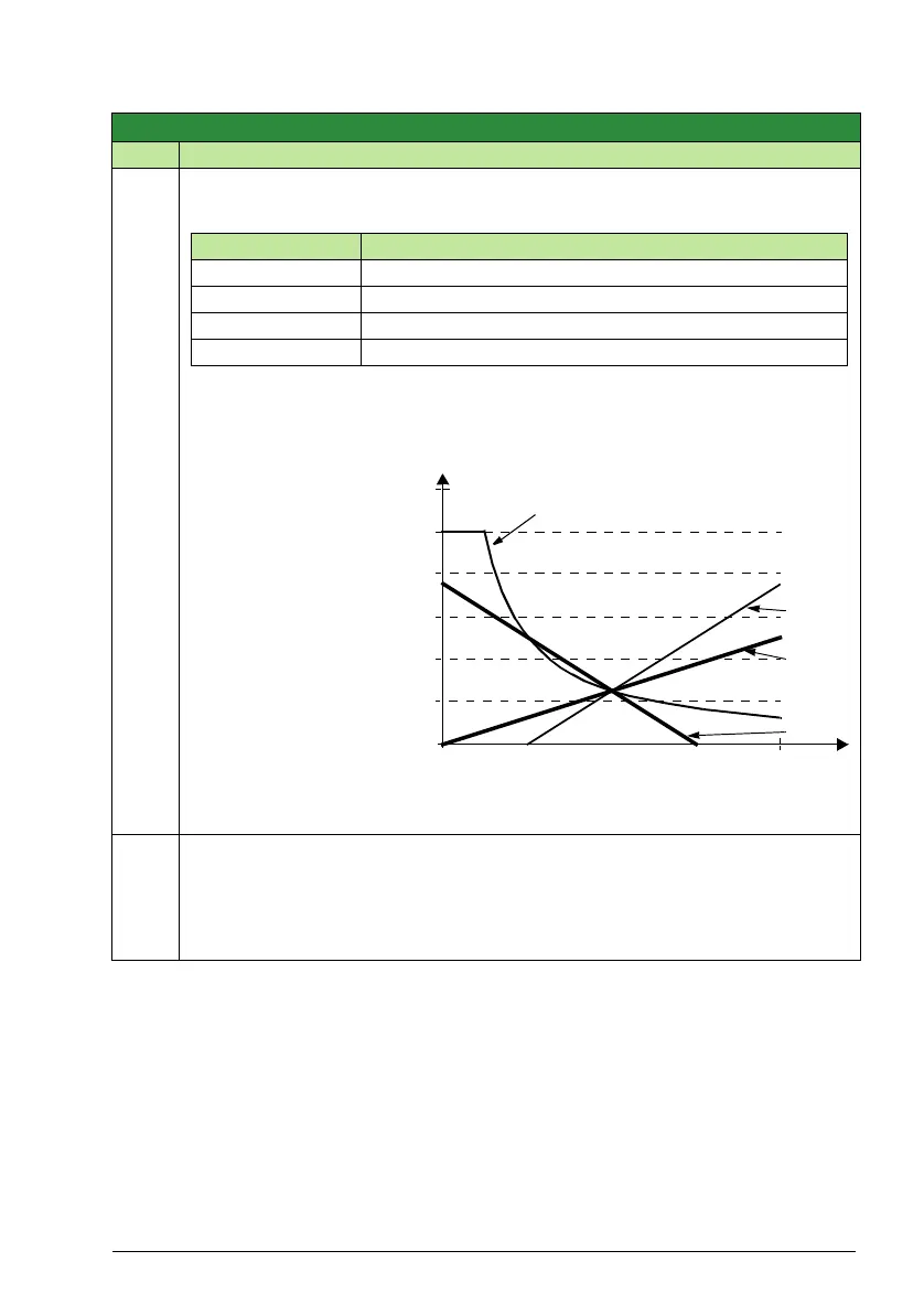
The figure shows the
reference source curves
for value settings 9, 10,
and 14…17, where:
•C = 25%.
• Parameter 4012
SETPOINT MIN = 0.
• Parameter 4013
SETPOINT MAX = 0.
• B varies along the
horizontal axis.
31 = DI4U, 5D(NC) – See
selection
DI3U,4D(NC).
32 = FREQ INPUT – Frequency limit.
4011
INTERNAL SETPNT
-3276.8 … 3277.7% 0.1% 40.0%
Selects a constant value as a process PID controller reference, when parameter 4010
SET POINT SEL value is set to INTERNAL.
• Unit and range depend on the unit and scale defined by parameters 4006 UNITS
and 4007 UNIT SCALE.
Group 40: Process PID set 1
Code Description Range Resolution Default S
Value Setting AI reference is calculated as following:
C + B C value + (B value - 50% of reference value)
C * B C value * (B value / 50% of reference value)
C - B (C value + 50% of reference value) - B value
C / B (C value * 50% of reference value) / B value
120
100
80
60
40
20
0
0
100%
9, 14 (+)
16 (-)
10, 15 (*)
17 (/)
B