Actual signals and parameters 231
4005
ERROR VALUE INV
0, 1 - 0
Selects either a normal or inverted relationship between the feedback signal and the
drive speed.
0 = NO – Normal, a decrease in feedback signal increases drive speed. Error = Ref -
Fbk
1 = YES – Inverted, a decrease in feedback signal decreases drive speed. Error = Fbk
- Ref
4006
UNITS
0…31 - 4
Selects the unit for the PID controller actual values. (PID1 parameters 0128, 0130, and
0132).
• See parameter 3405 OUTPUT1 UNIT for list of available units.
4007
UNIT SCALE
0…4 1 1
Defines the decimal point location in PID
controller actual values.
• Enter the decimal point location counting in
from the right of the entry.
• See table for example using pi (3.14159).
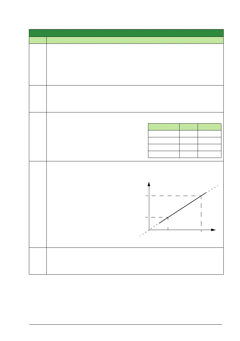
4008
0 % VALUE
-3276.8 …3276.7 - -
Defines (together with the next
parameter) the scaling applied to the
PID controller’s actual values (PID1
parameters 0128, 0130, and 0132).
• Units and scale are defined by
parameters 4006 UNITS and 4007
UNIT SCALE.
4009
100 % VALUE
-3267.8 …3276.7 - -
Defines (together with the previous parameter) the scaling applied to the PID
controller’s actual values.
• Units and scale are defined by parameters 4006 UNITS and 4007 UNIT SCALE.
Group 40: Process PID set 1
Code Description Range Resolution Default S
4007 value Entry Display
000033
100313.1
203143.14
3 3142 3.142
Internal scale (%)
100%
0%
-1000%
+1000%
4008
Scale (4007)
Units (4006)
4009