52 Electrical installation
Frequency input
If DI5 is used as a frequency input, see section Frequency input on page 111 for how
to set parameters accordingly.
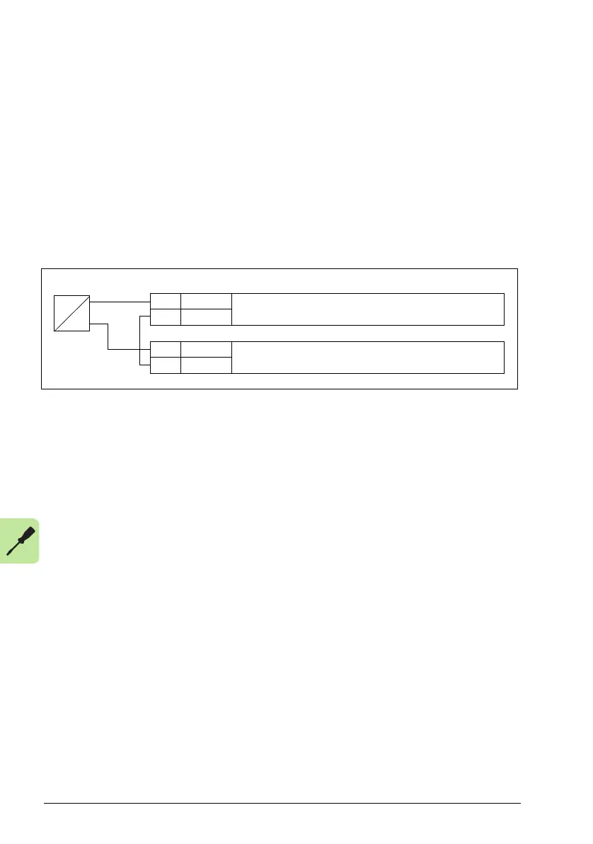
Connection example of a two-wire sensor
HVAC default, supply fan, return fan, cooling tower fan, condenser, booster pumps,
PFA control, internal timer, dual setpoint with PID, E-Clipse and dual setpoint with PID
and constant speeds macros (see section Application macros on page 79) use
analog input 2 (AI2). The macro wiring diagrams for these macros show the
connection when a separately powered sensor is used. The figure below gives an
example of a connection using a two-wire sensor.
Note: The sensor is supplied through its current output. Thus the output signal must
be 4…20 mA.
X1A
5 AI2 Process actual value measurement or reference,
4…20 mA, R
in
= 100 ohm
6GND
…
9 +24V Auxiliary voltage output, non-isolated,
+24 V DC, max. 200 mA
10 GND
P
I
4…20 mA
 Loading...


