Actual signals and parameters 215
2005 OVERVOLT
CTRL
Activates or deactivates the overvoltage control of the
intermediate DC link.
Fast braking of a high inertia load causes the voltage to rise
to the overvoltage control limit. To prevent the DC voltage
from exceeding the limit, the overvoltage controller
automatically decreases the braking torque.
Note: If a brake chopper and resistor are connected to the
drive, the controller must be off (selection DISABLE) to
allow chopper operation.
ENABLE
DISABLE Overvoltage control deactivated 0
ENABLE
Overvoltage control activated
1
2006 UNDERVOLT
CTRL
Activates or deactivates the undervoltage control of the
intermediate DC link.
If the DC voltage drops due to input power cut off, the
undervoltage controller will automatically decrease the
motor speed in order to keep the voltage above the lower
limit. By decreasing the motor speed, the inertia of the load
will cause regeneration back into the drive, keeping the DC
link charged and preventing an undervoltage trip until the
motor coasts to stop. This will act as a power-loss ride-
through functionality in systems with a high inertia, such as
a centrifuge or a fan. See section Motor identification on
page 135.
ENABLE(
TIME)
DISABLE Undervoltage control deactivated 0
ENABLE(TIME) Undervoltage control activated. The undervoltage control is
active for 500 ms.
1
ENABLE Undervoltage control activated. No operation time limit. 2
2007 MINIMUM
FREQ
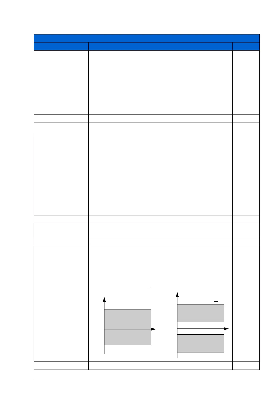
Defines the minimum limit for the drive output frequency.
A positive (or zero) minimum frequency value defines two
ranges, one positive and one negative.
A negative minimum frequency value defines one speed
range.
Note: MINIMUM FREQ < MAXIMUM FREQ.
0.0 Hz
-500.0…500.0 Hz Minimum frequency 1 = 0.1 Hz
All parameters
No. Name/Value Description Def/FbEq
2008
2007
0
f
2008
value is < 0
2007 value is > 0
f
2008
2007
0
-(2007)
-(2008)
t
t
Allowed
frequency range
Allowed
frequency range
Allowed
frequency range