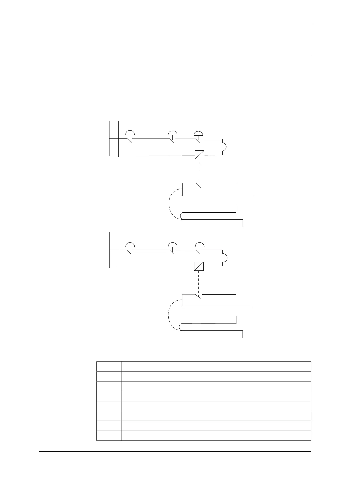
Connection of ES1/ES2 on panel unit
The diagram below shows the terminals for the emergency circuits.
The supply from internal 24V (X1:2/X2:6) and 0V (X1:6/X2:2) is displayed. For an
ext. supply, X1:1 / X2:5 is connected to ext. 24V, and X1:5 / X2:1 is connected to
ext. 0V.
24V
24V
0V
0V
X1:2
X1:6
X1:1
X1:5
X1:7
X1:8
24V
A
B C D
D
X1:4
E
24V
X2:7
X2:8
0V
X2:4
F
B
X2:2
X2
:3
C
X2:2
G
H
J
X2:1
X2:6 X2:5
X1:2
X1:3
0V
xx1000001009
InternalA
Ext stopB
FlexPendantC
CabinetD
ES1 internalE
Run chain 1 topF
InternalG
ES2 internalH
Continues on next page
Product manual - IRC5 Compact 83
3HAC047138-001 Revision: G
© Copyright 2009-2017 ABB. All rights reserved.
2 Installation and commissioning
2.6.8 The MOTORS ON/MOTORS OFF circuit
Continued