- 92 -
000839BG
5 - Installation
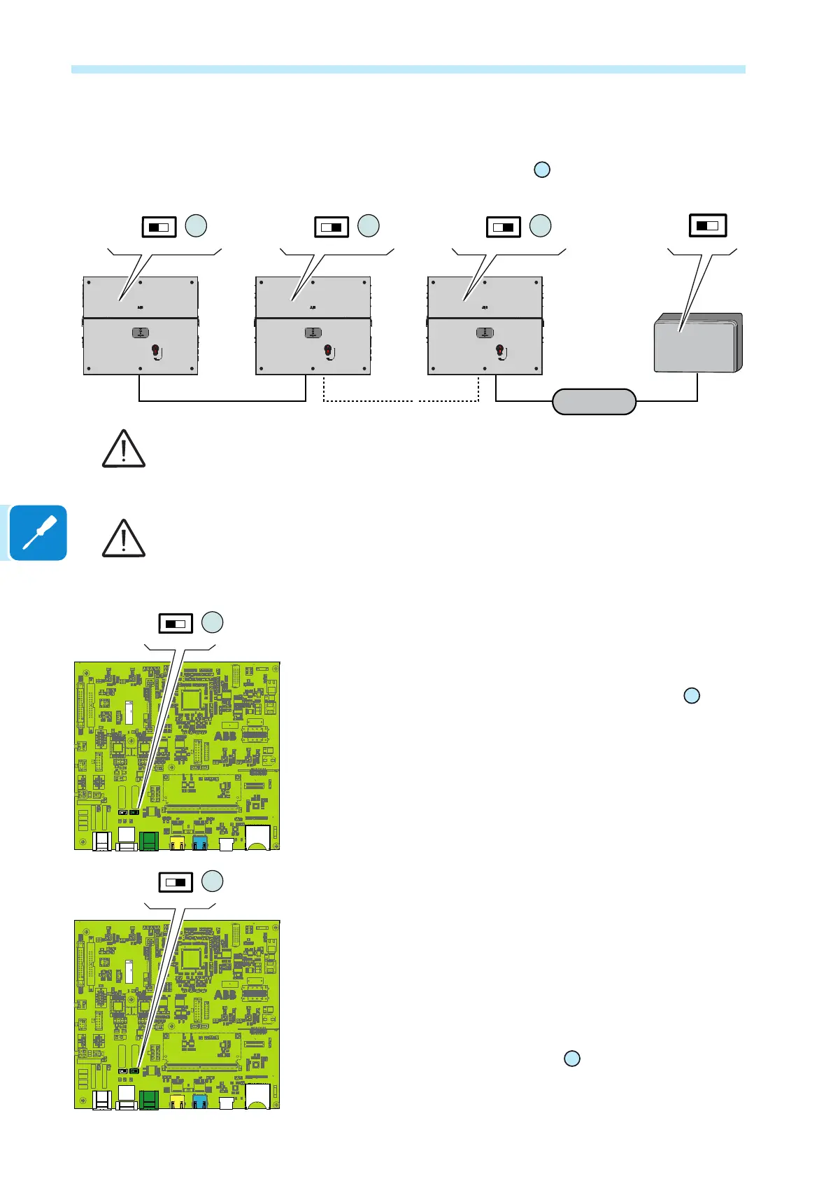
Connect all the units of the RS485 chain in accordance with the daisy-
chain model observing the correspondence between the signals, and
activate the termination resistance of the communication line in the nal
element of the chain by switching the
35
switch in the ON position.
J2 X1
X2
S5S4
J7
J1
J5 J6
1
2
1
8
7
432
ZGN.V2Q15.2
Monitoring
system
ON
OFF
S5
ON
OFF
120.0
TERM.
RS485
35
ON
OFF
S5
35
J2 X1
X2
S5S4
J7
J1
J5 J6
1
2
1
8
7
432
ZGN.V2Q15.2
ON
OFF
S5
35
ON
OFF
S5
35
ON
OFF
S5
35
The communication line must also be terminated on the rst element of the chain which
normally corresponds to the monitoring device.
It is recommended not to exceed a length of 1000m for the communication line.
The maximum number of inverters that can be connected to the same RS485 line is 62.
In case of longher communication line and/or in case of a large number of connected inverters
to the same line it could be necessary to add a RS485 amplier to guarantee the performance
of the communication line.
When connecting a single inverter to the monitoring system, activate the
communication line resistance terminal by setting the switch
35
(to the
ON position).
Set a different RS485 address on each inverter in the chain. No inverter
can have “Auto” as an address. An address can be freely chosen
between 2 and 63.
The setting of the address on the inverter is done through the integrated
Web User Interface (refer to chapter “Web User Interface”).
When an RS-485 connection is being used, if one or more inverters are
added to the system at a later time, it is necessary to remember to reset
to OFF the switch of the termination resistance being used (1) or (2) on
the inverter which previously was the last in the system.
Each inverter is shipped with the RS485 address pre-set to two (2) and
with the resistance terminal setting Switch
35
in the OFF position.
J2 X1
X2
S5S4
J7
J1
J5 J6
1
2
1
8
7
432
ZGN.V2Q15.2
ON
OFF
S5
35
J2 X1
X2
S5S4
J7
J1
J5 J6
1
2
1
8
7
432
ZGN.V2Q15.2
ON
OFF
S5
35