solutions are aimed for connections to a multiplexer, which in turn is connected to a
telecommunications transmission network (for example, SDH or PDH).
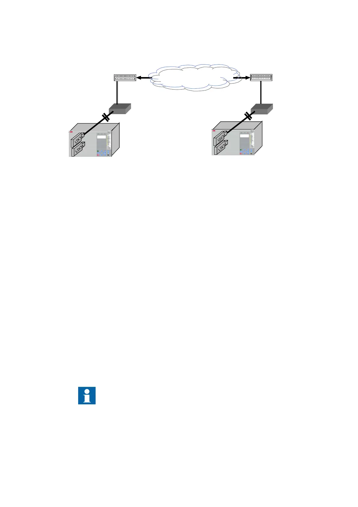
Telecom. Network
*) *)
Multiplexer Multiplexer
en05000527-2.vsd
*) Converting optical to galvanic G.703
IEC05000527 V2 EN-US
Figure 213: LDCM with an external optical to galvanic converter and a multiplexer
When an external modem G.703 or X21 is used, the connection between LDCM and the modem
is made with a multimode fiber of max. 3 km length. The IEEE/ANSI C37.94 protocol is always
used between LDCM and the modem.
Alternatively, a LDCM with X.21 built-in converter and micro D-sub 15-pole connector output
can be used.
19.1.3 Setting guidelines
M12454-3 v5.1.1
ChannelMode
: This parameter can be set
Normal
or
Blocked
. Besides this, it can be set
OutOfService
which signifies that the local LDCM is out of service. Thus, with this setting, the
communication channel is active and a message is sent to the remote IED that the local IED is
out of service, but there is no COMFAIL signal and the analog and binary values are sent as
zero.
TerminalNo
: This setting shall be used to assign an unique address to each LDCM, in all current
differential IEDs. Up to 256 LDCMs can be assigned a unique number. Consider a local IED with
two LDCMs:
• LDCM for slot 302: Set
TerminalNo
to 1 and
RemoteTermNo
to 2
• LDCM for slot 303: Set
TerminalNo
to 3 and
RemoteTermNo
to 4
In multiterminal current differential applications, with 4 LDCMs in each IED, up to 20 unique
addresses must be set.
The unique address is necessary to give high security against incorrect
addressing in the communication system. Using the same number for setting
TerminalNo
in some of the LDCMs, a loop-back test in the communication
system can give incorrect trip.
RemoteTermNo
: This setting assigns a number to each related LDCM in the remote IED. For
each LDCM, the parameter
RemoteTermNo
shall be set to a different value than parameter
Section 19 1MRK 511 358-UEN A
Remote communication
432
Application manual
 Loading...


