1MAC309294-MB F Section 4
Protection functions
RER620 191
Technical Manual
When the operation timer has reached the value set by Trip delay time in the DT mode or
the maximum value defined by the IDMT, the TRIP (OPERATE) output is activated.
When the user-programmable IDMT curve is selected, the trip time characteristics are
defined by the parameters Curve parameter A, Curve parameter B, Curve parameter C,
Curve parameter D and Curve parameter E.
If a drop-off situation occurs, that is, a fault suddenly disappears before the trip delay is
exceeded, the reset state is activated. The behavior in the drop-off situation depends on the
selected trip time characteristics. If the DT characteristics are selected, the reset timer runs
until the set Reset delay time value is exceeded. If the drop-off situation exceeds the set
Reset delay time, the timer is reset and the PICKUP output is deactivated.
When the IDMT trip time curve is selected, the functionality of the timer in the drop-off
state depends on the combination of the Type of reset curve and Reset delay time settings.
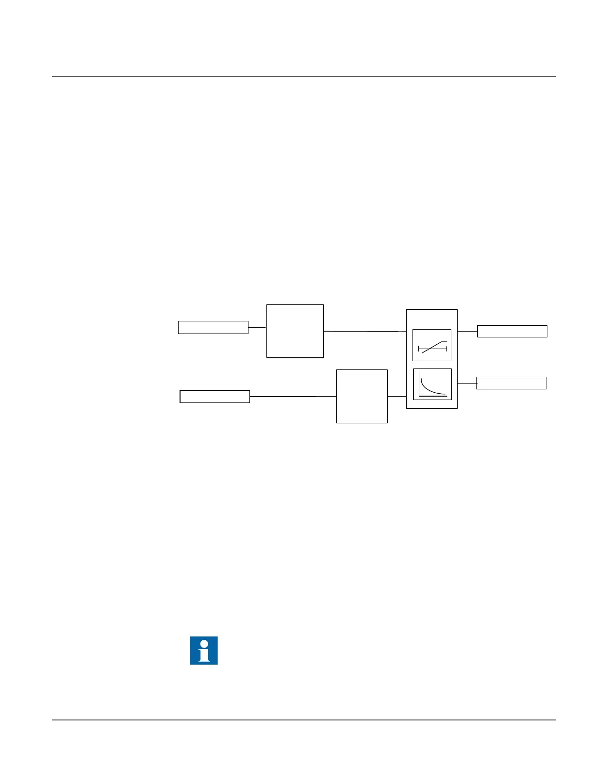
Single Phase Mode
Figure 87: Functional module diagram (Single Phase)
The following description holds good when single phase mode is chosen for the recloser.
The fundamental frequency component of the measured single-phase voltage is compared
to the set value of the Start (pickup) value setting phase-wise. The Relative hysteresis
setting can be used for preventing unnecessary oscillations if the input signal slightly
differs from the Pickup value setting. After leaving the hysteresis area, the pickup
condition has to be fulfilled again and it is not sufficient for the signal to only return to the
hysteresis area.
The Voltage selection setting is used for selecting phase-to-ground or phase-to-phase
voltages for protection.
For the voltage IDMT operation mode, the used IDMT curve equations contain
discontinuity characteristics. The Curve Sat relative setting is used for preventing
undesired operation.
For a more detailed description of the IDMT curves and the use of the
Curve Sat Relative setting, see the General function block features section
in this manual.
V_A_AB
BLOCK
Level
detector
t
Timer
t
OPR_A-AB
ST_A_AB
Blocking
logic