Section 4 1MAC309294-MB F
Protection functions
266 RER620
Technical Manual
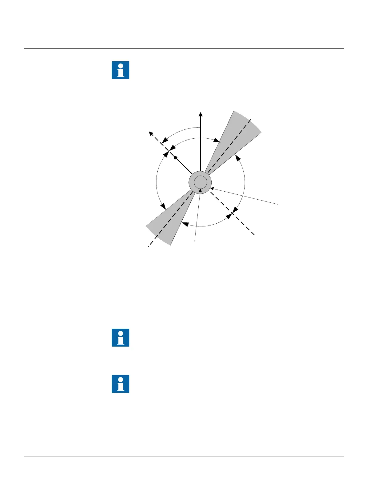
Figure 131: Configurable directional setting when “Neg. seq. volt.” selection is made
using
Pol signal Sel
When “Measured V
G
” or “Calculated V
N
” voltage selection is made using Pol signal Sel
setting, the Directional detector module compares the angle of the residual current to the
residual voltage. Using the residual voltage as reference the residual current angle is
compared to the Characteristic angle setting. If the angle difference is within the operating
sector selected by Directional mode setting, then enable signal is sent to the Timer.
The operating sector is defined by the settings Max forward angle, Max reverse angle, Min
forward angle, and Min reverse angle (see Figure 131). User selectable options for
Directional mode are “Forward” and “Reverse”.
The Characteristic angle is also known as Relay Characteristic Angle
(RCA), Relay Base Angle or Maximum Torque Line.
The “Measured IG” or “Calculated IN” (residual current) can be selected
using Io signal Sel setting.
The “Measured VG”, “Calculated VN” (residual voltage) can be selected
using Pol signal Sel setting.
The polarizing quantity (residual voltage) is inverted because of switched
voltage measurement cables, the correction can be done by setting the Pol
reversal setting to “True” which rotates polarizing quantity by 180
degrees.
-V
2
I
2
RCA=+45 deg
Max
forward
angle
Min
forward
angle
Max
reverse
angle
Min
reverse
angle
Backward
area
Forward
area
N
o
n
-
o
pe
r
a
t
i
n
g
ar
e
a
N
o
n
-
o
p
e
r
a
t
i
n
g
ar
ea
Min operate
voltage
Min operate
current
Characteristic
Angle/
Max torque line
Zero torque line