1MAC309294-MB F Section 4
Protection functions
RER620 265
Technical Manual
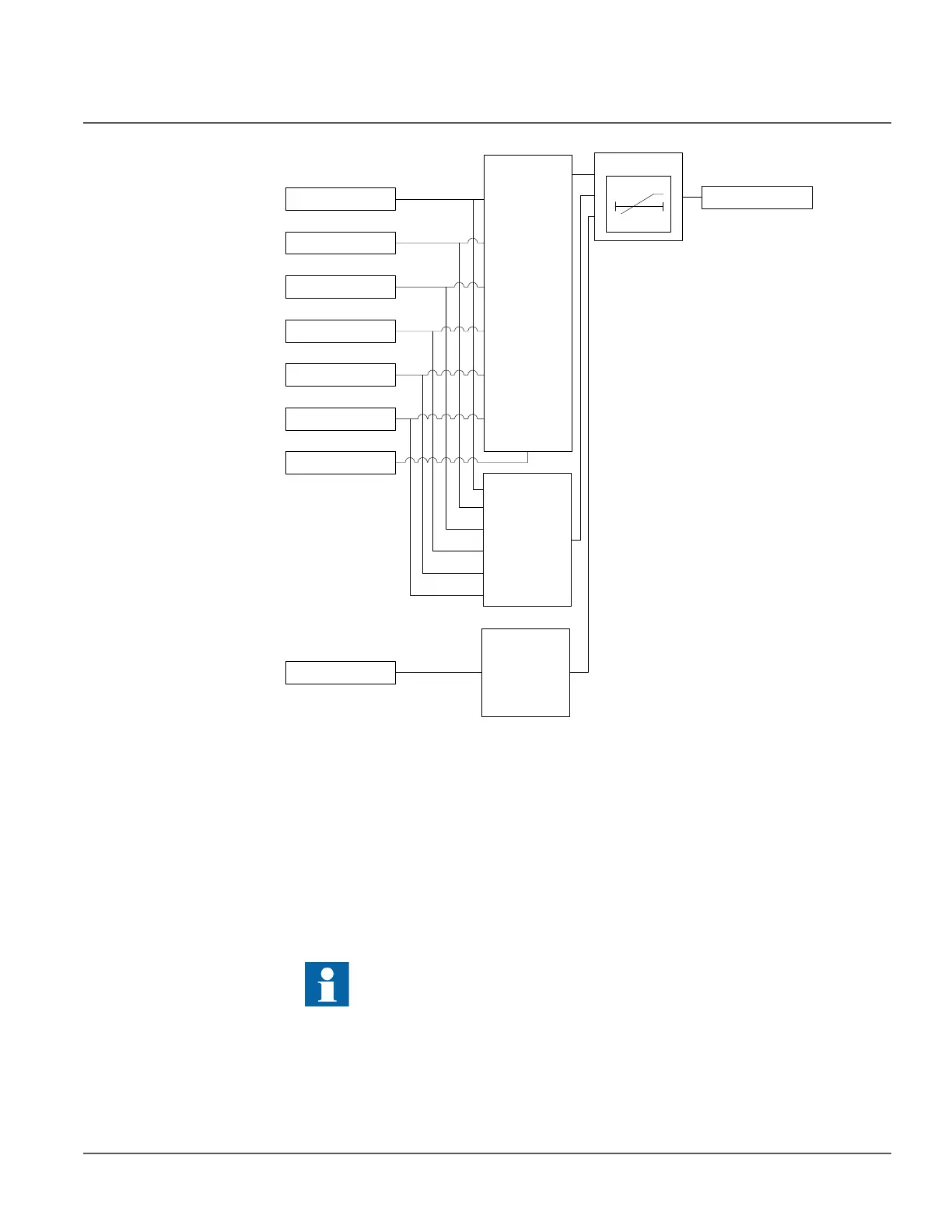
Figure 130: Functional module diagram
Directional detector
When “Neg. seq. volt.” selection is made using Pol signal Sel, the directional detector
module compares angle of negative sequence current (I
2
) to the negative sequence voltage
(-V
2
). Using the negative sequence voltage angle as the reference the negative sequence
current angle is compared to the Characteristic angle. If the angle difference is within the
operating sector selected by Direction mode setting then enable signal is sent to the Timer.
The operating sector is defined by the settings Max forward angle, Max reverse angle, Min
forward angle and Min reverse angle (see Figure 131). User selectable options for
Directional mode are “Forward” and “Reverse”.
The value of Characteristic angle should be chosen in such way that all the
faults in the operating direction are seen in the operating zone and all the
faults in the opposite direction are seen in the backward zone.
Directional
detector
VN
I2
BLOCK
RELEASE
Blocking
logic
IG
IN
RCA_CTL
Low level
blocking
t
Timer
VG
V2