Section 6 1MAC309294-MB F
Condition monitoring functions
362 RER620
Technical Manual
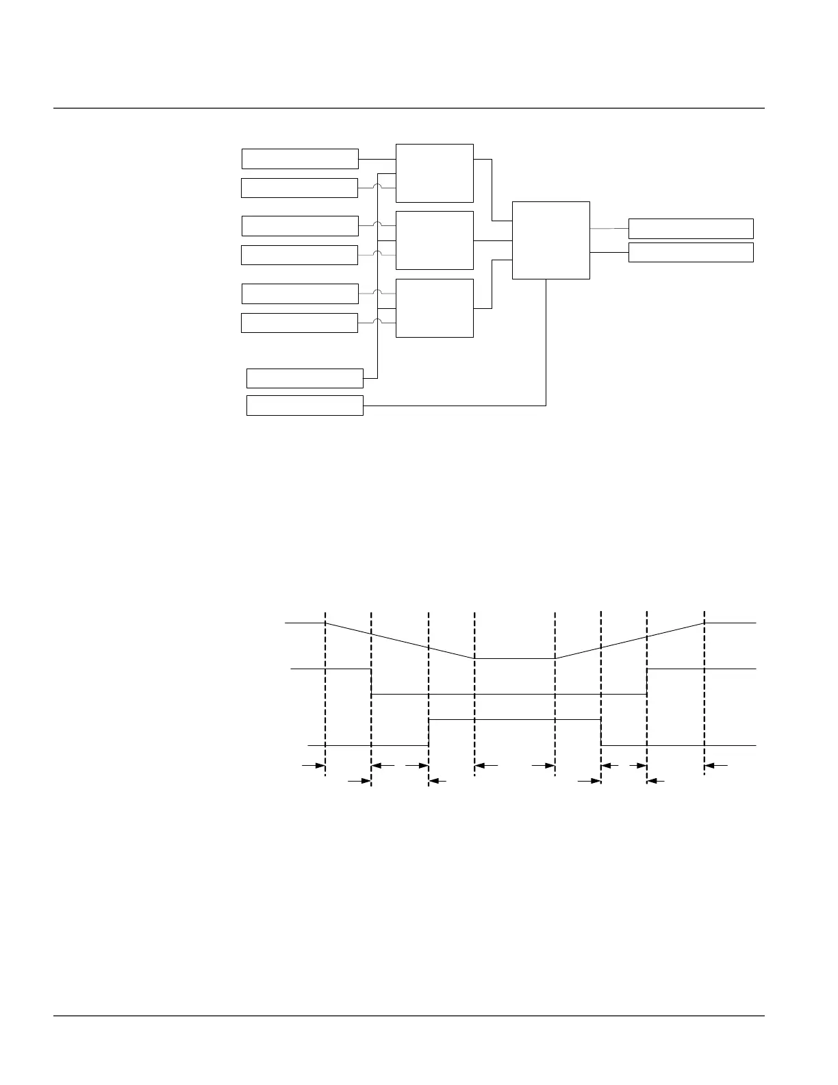
Figure 195: Functional module diagram for breaker contact travel time
Traveling time calculator
The contact travel time of the breaker is calculated from the time between auxiliary
contacts' state change. The open travel time is measured between the opening of the
POSCLOSE_A(_B,_C) auxiliary contact and the closing of the POSOPEN_A(_B,_C)
auxiliary contact. Travel time is also measured between the opening of the POSOPEN
auxiliary contact and the closing of the POSCLOSE_A(_B,_C) auxiliary contact.
Figure 196: Travel time calculation
There is a time difference t
1
between the start of the main contact opening and the opening
of the POSCLOSE_A(_B,_C) auxiliary contact. Similarly, there is a time gap t
2
between
the time when the POSOPEN_A(_B,_C) auxiliary contact opens and the main contact is
completely open. Therefore, in order to incorporate the time t
1
+t
2
, a correction factor
needs to be added with t
open
to get the actual opening time. This factor is added with the
Traveling
time (A)
calculator
POSCLOSE_A
RST_TRV_T
TRV_T_OP_ALM
TRV_T_CL_ALM
BLOCK
Alarm limit
check
POSOPEN_A
Traveling
time (B)
calculator
POSCLOSE_B
POSOPEN_B
Traveling
time (C)
calculator
POSCLOSE_C
POSOPEN_C
Main Contact (A)
POSCLOSE_A
0
1
0
1
POSOPEN_A
t
4
t
3
t
close
t
2
t
1
t
open
T_TRV_OP_A= t
open
+t
1
+t
2
T_TRV_CL_A= t
close
+t
3
+t
4
open
close
close