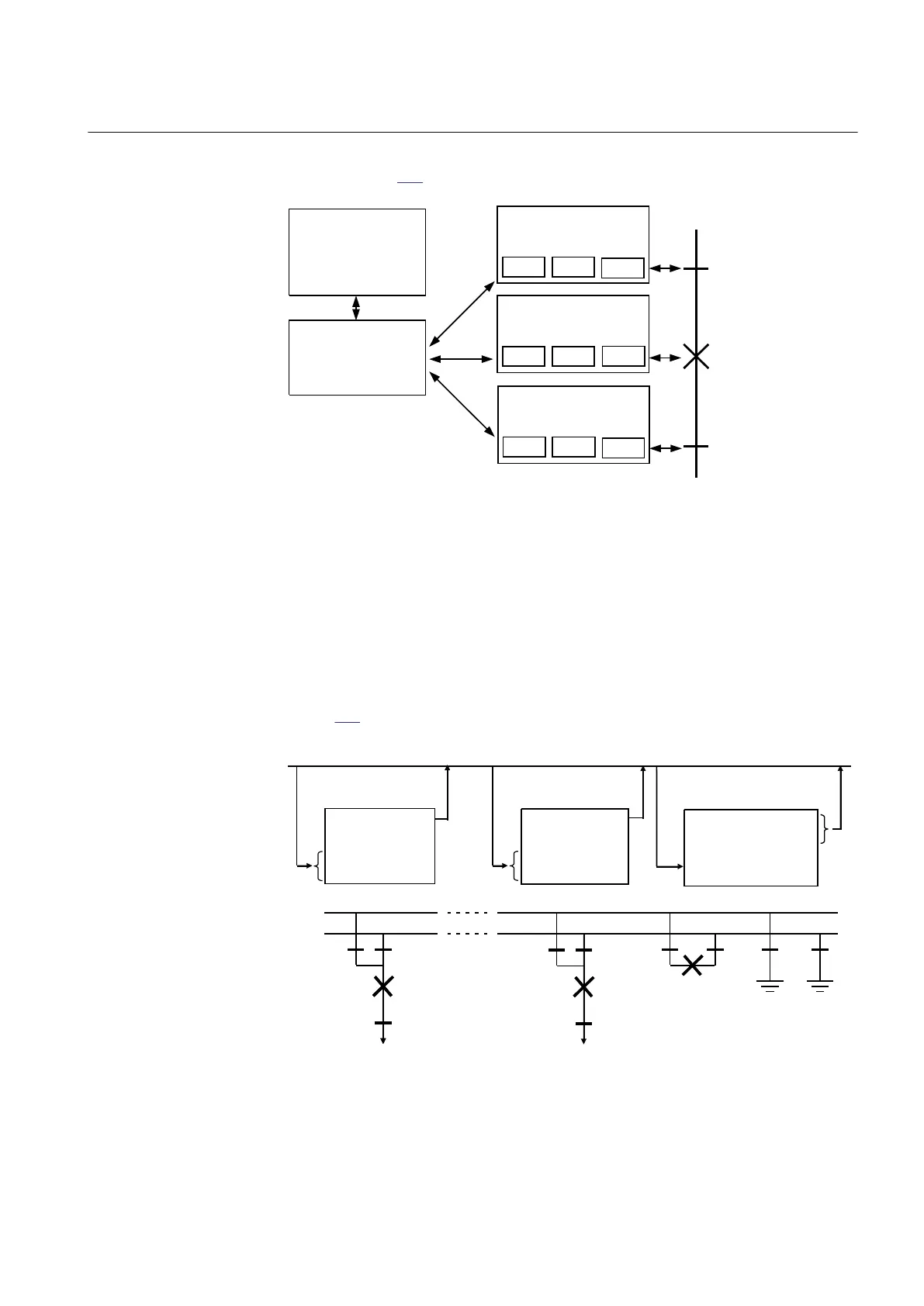
The interlocking module is connected to the surrounding functions within a bay as
shown in figure 148.
Interlocking
modules in
other bays
Interlocking
module
SCILO SCSWI
Apparatus control
modules
SXCBR
SCILO SCSWI
SXSWI
Apparatus control
modules
SCILO SCSWI
SXSWI
Apparatus control
modules
en04000526.vsd
IEC04000526 V1 EN
Figure 148: Interlocking module on bay level
Bays communicate via the station bus and can convey information regarding the
following:
• Unearthed busbars
• Busbars connected together
• Other bays connected to a busbar
• Received data from other bays is valid
Figure
149 illustrates the data exchange principle.
Disc QB1 and QB2 closed
WA1 not earthed
WA2 not earthed
WA1 and WA2 interconn
Disc QB1 and QB2 closed
WA1 not earthed
WA2 not earthed
WA1 and WA2 interconn
. . .
. .
Station bus
QB1
WA1
WA2
Bay 1 Bay n Bus coupler
WA1 unearthed
WA1 unearthed
WA1 and WA2 interconn
WA1 and WA2 interconn
in other bay
QB2
QA1
QB9
QB1
QB2
QA1
QB9
QB2
QB1
QA1
QC1
QC2
en05000494.vsd
IEC05000494 V1 EN
Figure 149: Data exchange between interlocking modules
1MRK 504 135-UEN A Section 12
Control
329
Technical manual