The main objectives of the circulating current method for parallel voltage control are:
1. Regulate the busbar or load voltage to the preset target value.
2. Minimize the circulating current in order to achieve optimal sharing of the
reactive load between parallel transformers.
The busbar voltage UB is measured individually for each transformer in the parallel
group by its associated TR8ATCC function. These measured values will then be
exchanged between the transformers, and in each TR8ATCC block, the mean value of
all UB values will be calculated. The resulting value U
Bmean
will then be used in each
IED instead of UB for the voltage regulation, thus assuring that the same value is used
by all TR8ATCC functions, and thereby avoiding that one erroneous measurement in
one transformer could upset the voltage regulation. At the same time, supervision of
the VT mismatch is also performed.
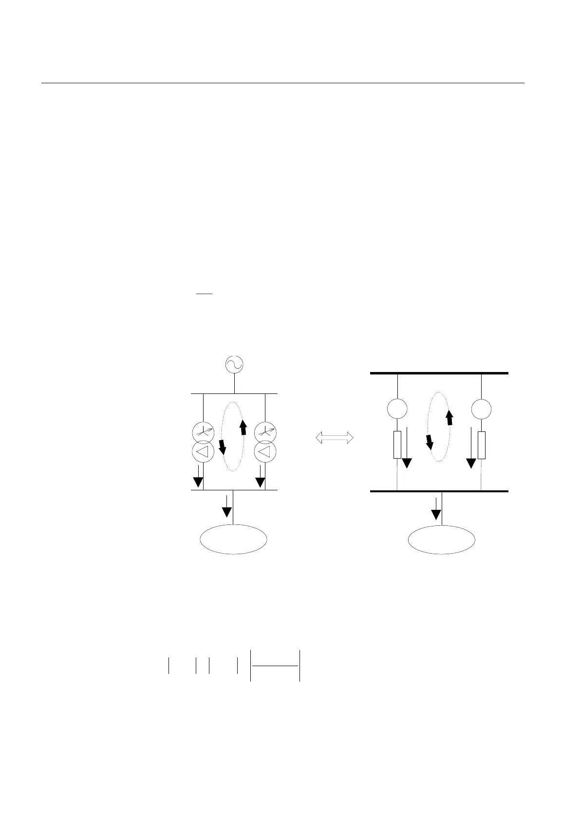
Figure
152 shows an example with two transformers connected in parallel. If
transformer T1 has higher no load voltage it will drive a circulating current which adds
to the load current in T1 and subtracts from the load current in T2.
Load
T1
T2
Load
+
+
IEC06000484_2_en.vsd
UB
UL
IT1 IT2
ICC...T2
ICC...T1
IL
UL
ICC...T2
ICC...T1
IL
UT1
ZT1
UT2
ZT2
IT1 IT2
IEC06000484 V2 EN
Figure 152: Circulating current in a parallel group of two transformers
It can be shown that the magnitude of the circulating current in this case can be
approximately calculated with the formula:
1 2
_ 1 _ 2
1 2
T T
cc T cc T
T T
U U
I I
Z Z
-
= =
+
EQUATION1866 V1 EN (Equation 86)
Section 12 1MRK 504 135-UEN A
Control
344
Technical manual