H7530/H7530D Condential 2-9
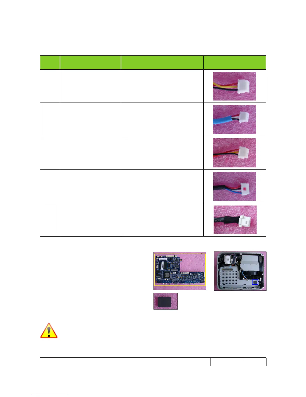
Item
Male Connector
on Main Board
The key feature Figure
F
DA Blower
(only for H7530D)
Compose of Red/Yellow/Black
Wire (3 pin)
G Lamp Blower
Compose of Red/White/Black
Wire and Blue wire tube (3 pin)
H System Fan
Compose of Red/Yellow/Black
Wire (3 pin)
I Thermal Sensor
Compose of Red/Black/White/
Blue Wire and Black wire tube
(4 pin)
J Lamp Driver Black wire tube (5 pin)
5. Disassemble the Main Board Module.
6. Remove the Audio Chip Thermal Pad
(as blue square).
NOTE: Circuit boards > 10 cm² has been highlighted with the yellow rectangle as
above image shows. Please detach the Circuit boards and follow local
regulations for disposal.