ACTsmart2 Operating and Installation Manual Rev. 2
Copyright © 2015 Access Control Technology Ltd.
TAMP
1 2
12-
24V
0V
N/O
COM
N/C
B
A
AUX
I/O2
Prog I/P
Aux I/O1
LK 2
LK 1
TAMP
1 2
12-
24V
0V
N/O
COM
N/C
B
A
AUX
I/O2
Prog I/P
Aux I/O1
LK 2
LK 1
A
B
SHIELD
SHIELD
SHIELD S
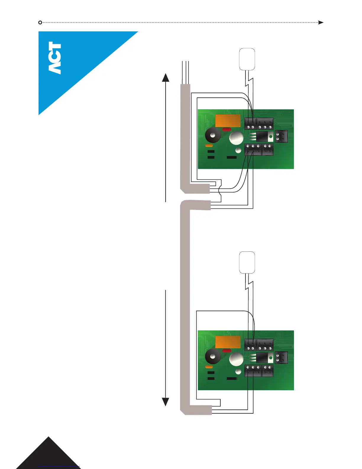
Network cable is single shielded twisted pair, Belden 9501 or similar.
Total cable length
maximum 1.4km
+12V
0V
B
A
B
A
B
A
B
When networking the ACTsmart2 units,
common the 0V of each ACTsmart2 to avoid
ground loop issues.
ACTsmart2 Network Installation Diagram
Do NOT use AC Power Supply.
MUST be 12V or 24V DC.
Continue daisy-chain to
remaining ACTsmart2 units
on the network (maximum 8).
DC Power
Supply Uni
t
+12V
0V
DC Power
Supply Uni
t
© Copyright of Access Control Technology Ltd 2015
Training is available on all ACT products - email training@act.eu for more information
20