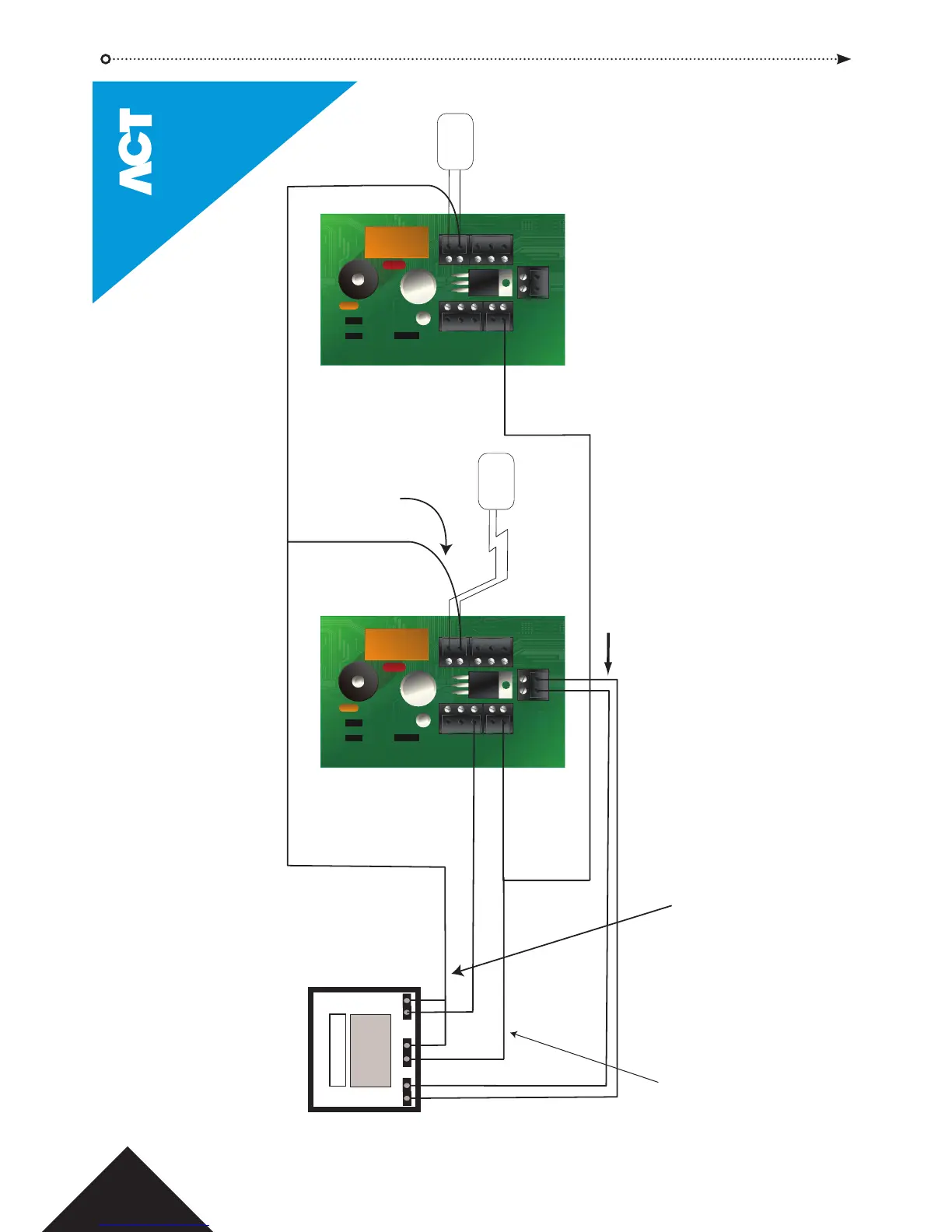
+12V
0V
Optional signal from the
alarm panel to indicate armed
or disarmed status. If 0V is
connected to ACTsmart2,
the panel is armed
.
Note:
0V line of ACTsmart2
system is connected
to the 0V of the alarm
panel.
Note:
To arm and disarm the Alarm Panel,
users must have the Arm Function.
Please refer to the manual to program
this function. The ACTsmart2 must
also be assigned the Arming Door
Option.
0V
Input
In this case AUX I/O 1 is programmed
as Panel Armed Input (see I/O Functions).
Common the 0V line of
each ACTsmart2 to avoid
Ground Loop issues.
While I/O 1 is active (connected to 0V), the door is locked.
The red LED flashes indicating that the panel is armed.
N/O
COMM
Connect Door Armed Output from ACTsmart2 to
is active, the door is locked and access is only
permitted to users with the Arm function.
In this case AUX I/O 2 is programmed as Door Armed
Output (see I/O Functions). The Door Armed Ouput
may also be programmed to pulse for 2 seconds (see
ACTsmart Options).
Connect Tamper on
ACTsmart2 to the panel.
DC Power
Supply Unit
DC Power
Supply Unit
ACTsmart2 Alarm Panel Wiring Diagram
© Copyright of Access Control Technology Ltd 2015
22