ACTsmart2 Operating and Installation Manual Rev. 2
Copyright © 2015 Access Control Technology Ltd.
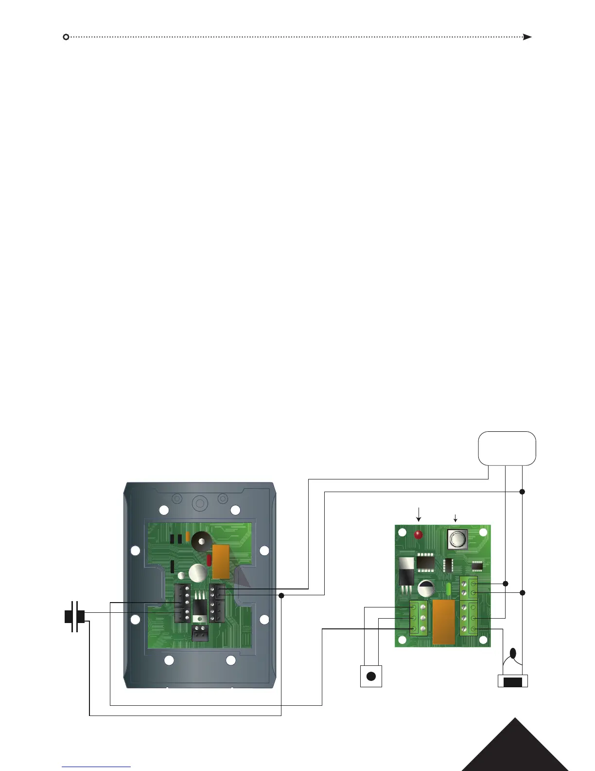
ACT Smart Lock Connection Diagram
The SmartLock improves the security of ACTSmart2 installations by allowing the installer to locate the lock
control relay inside a secure area. The SmartLock learns an ID code from the ACTSmart2 and only operates its’
relay when a valid card or PIN is presented to the ACTSmart2. Since the SmartLock is inside a secure area, an
attacker has no access to the lock control relay.
Installation
The normally open door release button should be connected to the SmartLock. When the input is activated,
the door will open for the Door Relay Time programmed into the ACTSmart. ACT recommends installing the
SmartLock inside the Power Supply Unit. Some PSUs can accomodate the Smartlock directly, otherwise drill
holes to suit the SmartLock, (5mm drill bit required).
For a Maglock, two fused outputs are required - one fused output for the ACTSmart2 and another for the Smartlock
and Maglock. This prevents a short from +12V to 0V on the ACTSmart2 side of the door from deenergising the
Maglock. Ensure that the Door Release wires are not accessible to an attacker.
The Data line from the SmartLock to the ACTSmart2 must be less than 30m.
Programming
1. Connect the ACTSmart2 and the SmartLock as in the diagram below and power up.
2. The red LED on the SmartLock will be on steady.
3. Program one of the AUX I/Os on the Smart2 for SmartLock operation. For AUX I/O 2 enter r followed by
the programming code (default code is 9999) and 5211 ar.
4. The red LED on the SmartLock ashes every second.
5. Press and hold the Programming button until the LED ashes rapidly.
The SmartLock is now programmed.
6. Remember to change the other AUX I/O and the Programmable Input from Door Release Button.
To set the Programmable Input to Door Contact enter r then the programming code and 500 ar.
To set AUX I/O 1 to Door Alarm enter r followed by the programming code and 5108 ar.
7. If the ACTSmart2 unit is ever replaced or defaulted, then repeat this procedure.
TAMP
1 2
12-
24V
0V
N/O
COM
N/C
B
A
AUX
I/O2
Prog I/P
Aux I/O1
LK 2
LK 1
0V
12-
24V
N/O
COM
N/C
PB
0V
Data
Red LED Programming
Button
Important!
Always Place Varistor
Across Lock Terminals
Power
Supply Unit
Door
Contact
Max. 30m
+12V Fuses 1
+12V Fuses 2
0V
Door Release Button
ACTsmart2 Unit
SmartLock
This illustration shows wiring for a normally energised lock (eg. maglock).
If a normally de-energised lock (doorstrike) is required, use the N/O relay contact.