ACTsmart2 Operating and Installation Manual Rev. 2
Copyright © 2015 Access Control Technology Ltd.
+12V
0V
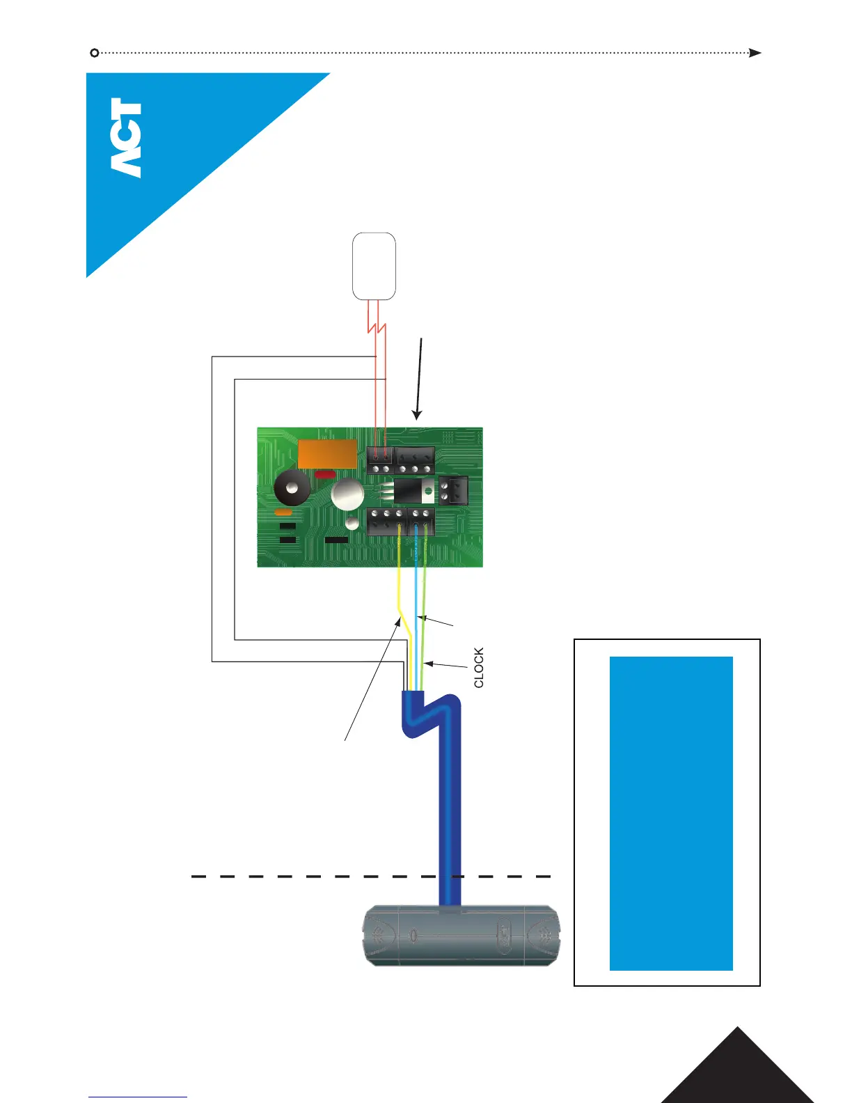
ACTpro-X Connections Diagram
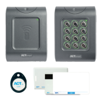
Reader
White
Green
Blue
Red
Black
Brown
Yellow
Orange
SENSE Not Used
CLOCK Aux I/O 1
DATA Programmable Input
+5V/+12V +12V
0V 0V
RED AUX I/O 2*
GREEN AUX I/O 2*
(Buzzer Control) Not Used
Wiring for ACTpro-X Readers
The Quick IO setup allows the ACTsmart2 unit to be connected to the
ACTpro family of Clock and Data readers. Enter
9999 536
.
To program the AUX I/O 2 for Green LED operation enter
9999 5218
.
Any ACTpro-X reader may be installed on the non-secure side of the door and
the ACTsmart2 installed inside the secure area. This prevents tampering
with the lock relay from the outside.
The diagram shows an ACTpro-X 1030 but any ACTpro-X product can be
used, including ACTpro-X PIN readers (ACTpro-X 1050 and ACTpro-X 1060).
Training is available on all ACT products - email training@act.eu for more information
Lock Contacts are secured.
Secure side of door
Readers may be a maximum of
100m when powered from +12V
*AUX I/O 2 may be programmed to follow either the Green or Red LED.
CLOCK (Green)
GREEN LED (Yellow)
DATA (Blue)
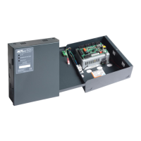
DC Power
Supply Unit
TAMP
1 2
12-
24V
0V
N/O
COM
N/C
B
A
AUX
I/O2
Prog I/P
Aux I/O1
LK 2
LK 1
© Copyright of Access Control Technology Ltd 2015