HARDWARE
and data buses)
plus
additional
control and
timing
signals.
These
include
interrupt
request
lines and control lines for
DMA
transfers.
Regulated supply voltages, for
the
System Board,
Keyboard
Unit,
Monitor
Unit,
floppy disk drivels)
and any
optional boards
connected
to
the
expansion slots, are
supplied from
the
power
supply
module
located
within
the
System
Unit.
A
switch
on
the
rear of
the
System
Unit
switches
the
mains
supply
through
to
the
power supply
module.
An
LED
in
the
centre
of
the
Keyboard acts as a
power supply
present
indicator.
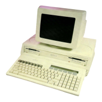
KEYBOARD
UNIT
The
Keyboard
Unit
provides
the
normal
interface
between
the
user
and
the
microcomputer.
The
keys of
the
Keyboard are divided
into
a
number
of functional groups, as
follows:
(aJ
The
standard
typewriter, cursor control
and
editing
keys occupying
the
majority
of
the
keyboard space.
(b)
The
calculator keypad located
at
the
far right of
the
keyboard.
(c)
A group of general
function
keys (grey keys located
above
the
typewriter
keys).
(d)
A group of
"soft"
function
keys. (The six
membrane
keys located directly below
the
MicroScreenJ.
The
system
reset
button
is located
on
the
right
hand
side
of
the
Keyboard
and
has
a
one
second delay to
prevent
the
accidental
resetting
of
the
system.
In addition
to
the
keys,
the
Keyboard
Unit
has
a
number
of display features,
which
are
the
six
LEDs
and
the
MicroScreen.
These
are
controlled
by software from
the
System
Unit,
which
transmits
the
display data
to
the
Keyboard via
the
serial link.
The
six LEDs are
used
to
signify
whether
the
six soft
function
keys are available for operation.
The
MicroScreen
is a
two
line
by forty
character
liquid
crystal display
unit,
with
each
character
consisting
of a five by seven
dot
matrix.