5-26 ADS TRITON+ Manual
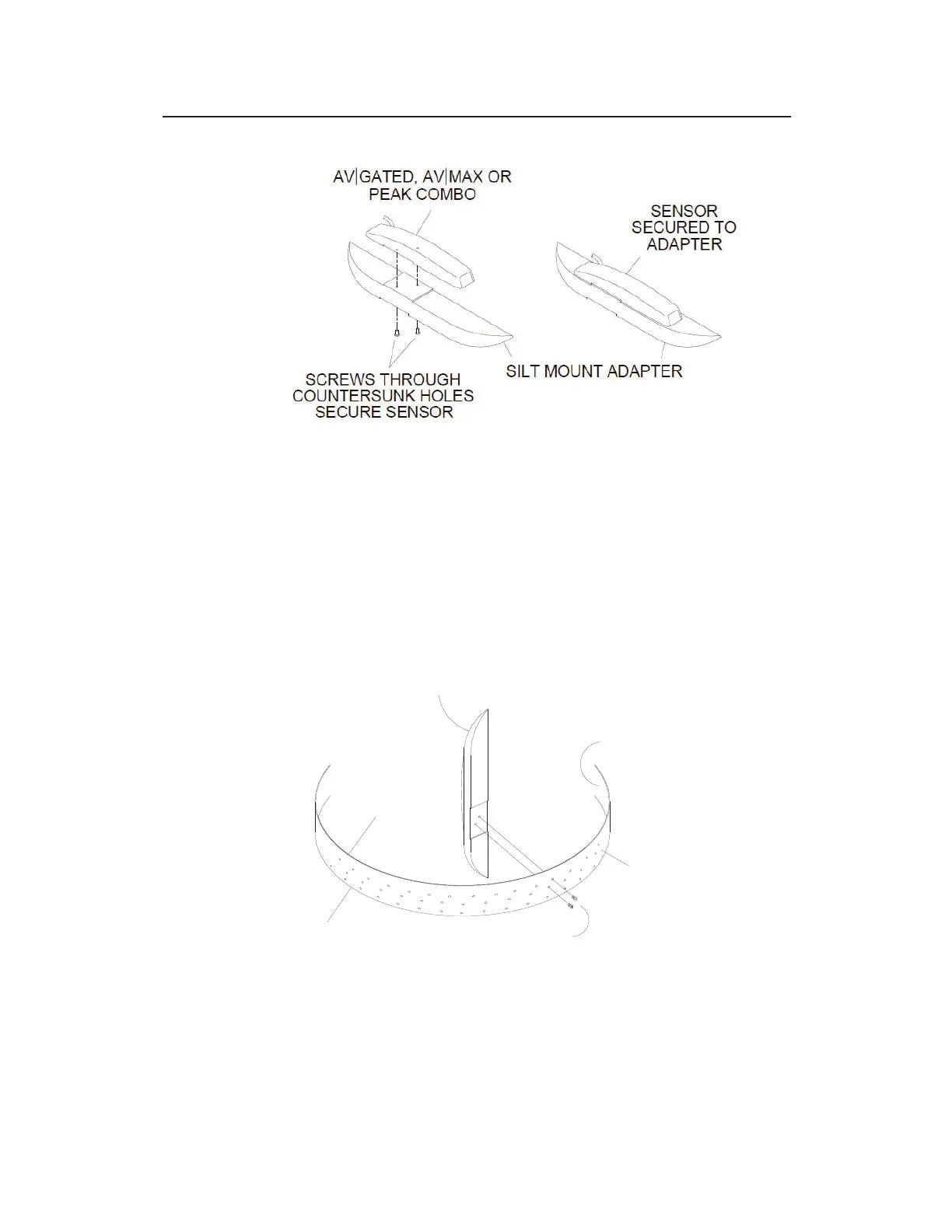
Properly seating and securing the AV|Gated/AV|Max/Peak Combo to the Silt
Mount Adapter
Use two M3 X 10mm stainless steel flathead screws (do
not substitute any other screws) to secure the adapter to
the ring at the appropriate location on the ring to ensure
the sensor will be positioned at 30 degrees up the left side
of the pipe and below the flow surface once installed. The
nose of the sensor should be facing the same direction as
the upstream edge of the ring.
Securing the AV|Gated, AV|Max or Peak Combo Sensor/Silt Mount Adapter
assembly to the ring
2. Orient the ring so that the ParaDepth, ParaFlow, Surface
Combo sensor/Ultrasonic Depth sensor mounting plate is
ADAPTER/SENSOR ASSEMBLY
UPSTREAM
EDGE
DOWNSTREAM
EDGE
INNER SURFACE OF
RING OR BAND
SCREWS
MOUNTING
OUTER SURFACE
OF
RING OR BAND