Sensor Installation and Connection 5-29
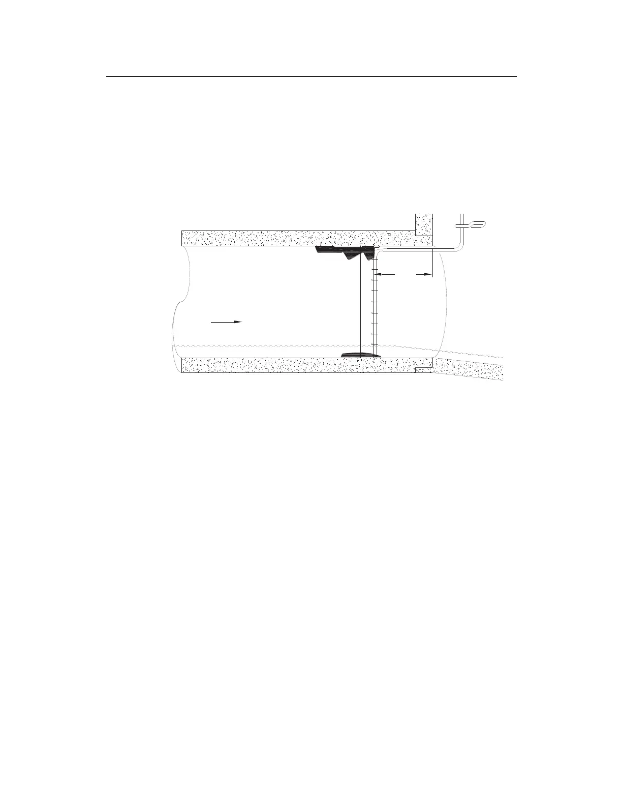
3. Place the ring in the input pipe at least 12 inches (305 mm)
upstream from the manhole or edge of the pipe with the
sensors facing upstream toward the oncoming flow. It must
be located far enough upstream from the manhole to minimize
the effect of the draw-down caused by a possible drop in the
manhole invert.
Installing the ring at least 12 inches (305 mm) upstream from the manhole
invert
Keep the following in mind:
The installed AV|Gated sensor must be positioned in the
bottom, center of the pipe and cannot exceed +/- 5
degrees from the 6:00 position. If a greater rotation
beyond +/- 5 degrees is needed, then a Silt Mount Adapter
must be used. Install the AV|Gated sensor and then verify
the sensor is correctly positioned. After activating the
monitor, perform a Diagnostic reading on the AV|Gated
Ultrasonic sensor and verify the Sensor Slope and Sensor
Rotation values are not greater than 5.0. See Chapter 4,
Running Sensor Diagnostics for more information.
Be sure to mount the ParaDepth, ParaFlow, Surface
Combo sensor/Ultrasonic Depth Sensor at the top (crown)
of the pipe and to mount the AV|Gated, AV|Max, and Peak
Combo sensors as close as possible to the bottom center of
the pipe, above any silt present and below the flow surface
(during minimum flows).
FLOW
12"